Daewoo Nubira. Manual - part 238


  Index      Daewoo     Daewoo Nubira - service repair manual


Search            


Content   ..  236  237  238  239   ..


Daewoo Nubira. Manual - part 238


FRONT SUSPENSION  2C – 29

DAEWOO V–121 BL4

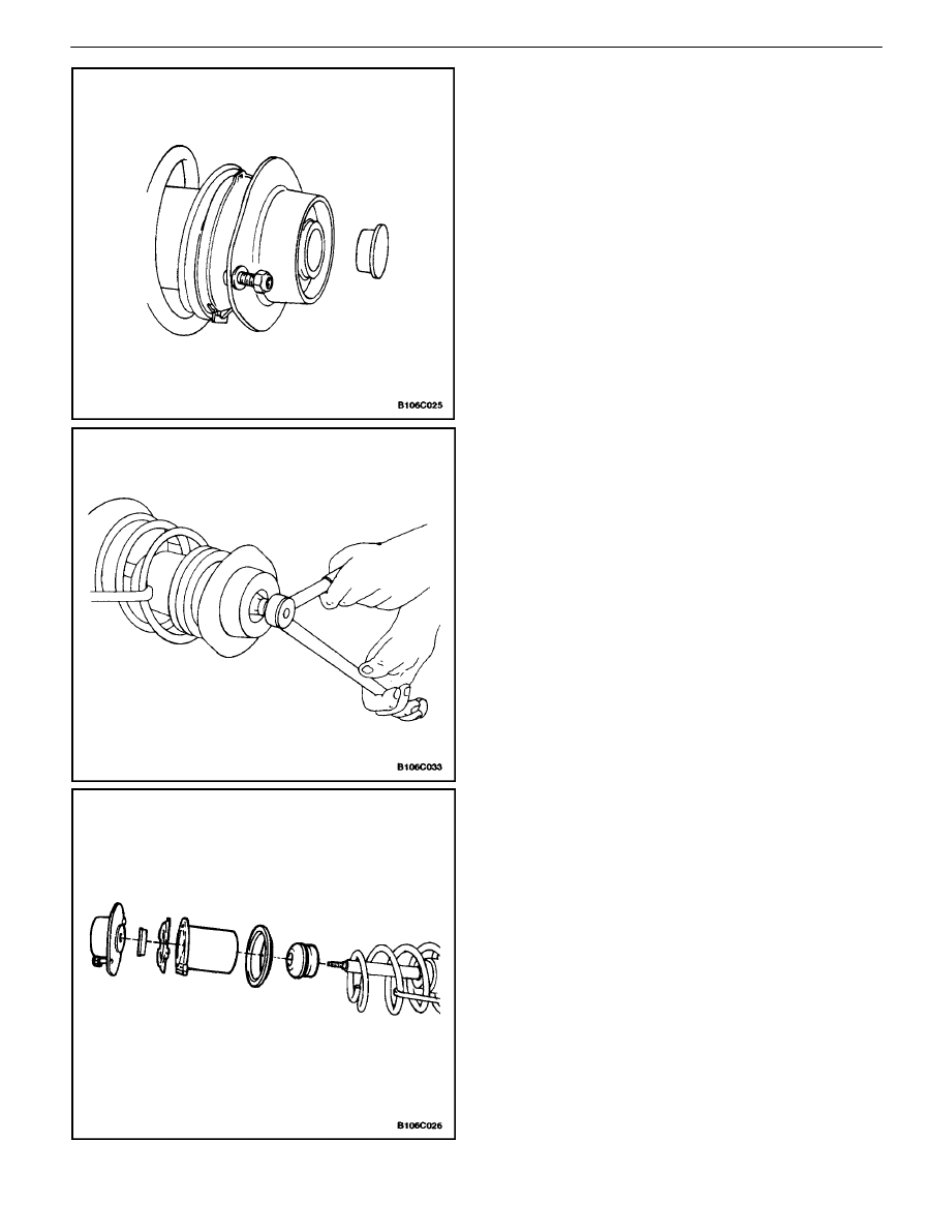
3.  Compress the front spring with the spring compres-

sor KM–329–A.

4.  Remove the dust cover from the bearing assembly.

5.  Use an open end wrench to hold the threaded pis-

ton rod while removing the piston rod nut and the
washer with a commercially available double ring
spanner, sharply offset.

Important : Record the position of the front spring locator
relative to the strut assembly–to–knuckle bracket. Place
the front spring locator back in the same position during
assembly.

6.  Remove the upper strut mount, the mount bearing,

the upper spring seat, the front spring locator, the
upper ring insulator, and the hollow bumper.

2C – 30

I

FRONT SUSPENSION

DAEWOO V–121 BL4

7.  Release the spring.
8.  Remove the spring and the lower ring insulator.

Assembly Procedure

1.  Install the lower ring insulator and the spring.
2.  Compress the spring using the spring compressor

KM–329–A.

3.  Install the hollow bumper, the upper ring insulator,

the front spring locator, the upper spring seat, the
upper strut mount, and the mount bearing. Be sure
the upper spring seat is clipped to the front spring
locator.

FRONT SUSPENSION  2C – 31

DAEWOO V–121 BL4

4.  Install the piston rod nut.

Tighten

Tighten the piston rod nut to 75 N

S

m (55 lb–ft).

5.  Remove the dust cover from the bearing assembly.
6.  Release the spring compressor KM–329–A.
7.  Remove the strut assembly from the spring com-

pressor KM–329–A.

8.  Install the strut assembly onto the vehicle. Refer to

”Strut Assembly” in this section.

2C – 32

I

FRONT SUSPENSION

DAEWOO V–121 BL4

KNUCKLE

Disassembly Procedure

1.  Remove the knuckle assembly from the vehicle.

Refer to”Knuckle Assembly” in this section.

2.  Remove the rotor. Refer to Section 4D, Front Disc

Brakes.

3.  Remove the hub and bearing assembly. Refer to

”Hub and Bearing” in this section.

4.  Remove the brake splash shield. Refer to Section

4D, Front Disc Brakes.

Assembly Procedure

1.  Install the brake splash shield. Refer to Section 4D,

Front Disc Brakes.

2.  Install the hub and bearing assembly. Refer to ”Hub

and Bearing” in this section.

3.  Install the rotor. Refer to Section 4D, Front Disc

Brakes.

4.  Install the knuckle assembly onto the vehicle. Refer

to ”Knuckle Assembly” in this section.

CROSSMEMBER

Disassembly Procedure

1.  Remove the crossmember assembly from the ve-

hicle. Refer to ”Crossmember Assembly”  in this
section.

2.  Remove the stabilizer clamp bolts. Remove the sta-

bilizer clamps, the stabilizer bar, and the insulators.

3.  Remove the control arm front nuts and the bolts.


Content   ..  236  237  238  239   ..