Daewoo Nubira. Manual - part 160


  Index      Daewoo     Daewoo Nubira - service repair manual


Search            


Content   ..  158  159  160  161   ..


Daewoo Nubira. Manual - part 160


Description

Page

Fuel Level Sensor Procedures

6 of 7

August, 2001

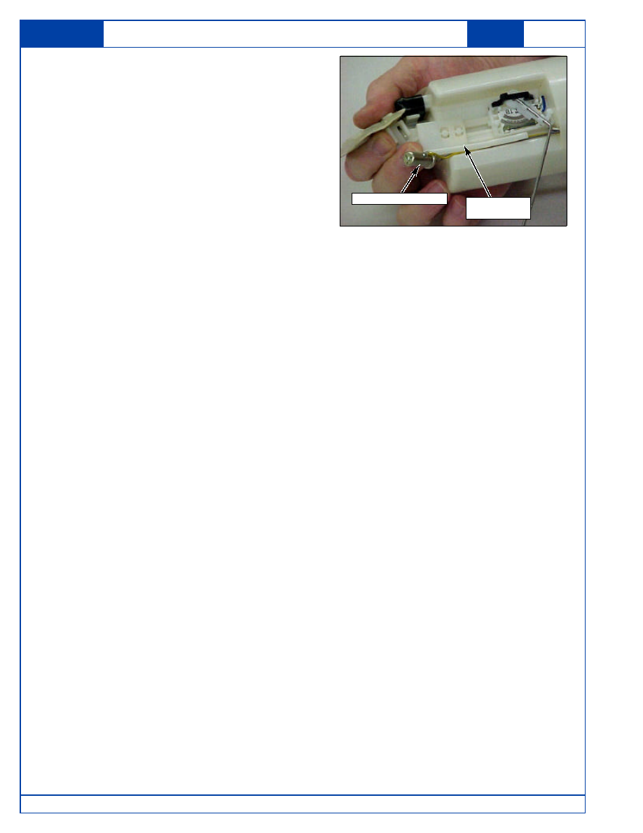
16. Guide the Low Fuel Level Sensor Bracket

onto the retaining rail on the Fuel Pump
Module Body.  An audible "click" will be heard
as it locks into it’s proper position.

17. Reinsert the Low Fuel Level Sensor onto its

bracket.

18. Test the new Fuel Level Sensor by using the

procedure described in steps 18 through 23 of
the Fuel Level Sensor Diagnostic Procedure
before reinstalling the Fuel Pump Module into
the Fuel Tank.

Low Fuel Level
Sensor Bracket

Low Fuel Level Sensor

19. Using a new O-ring, carefully reinstall the Fuel Pump Module into the Fuel Tank.  Take care

not to damage the O-ring or bend the Fuel Level Sensor Float Arm.

CAUTION: Removing components from a sealed fuel system exposes fuel vapors to

outside oxygen and possible sources of combustion.  A fuel system should
only be opened in a properly ventilated area.  Special caution should be
used when removing components from a fuel tank or fuel system. Removal
of such components should only be done away from open flame (torches,
lit cigarettes, heater pilots or other flames however minor) or sparks
(mechanical, electrical or otherwise) that could cause fuel vapors to ignite.

20. Using a suitable hammer and brass drift, reinstall the Fuel Pump Module Retaining Ring by

rotating it clockwise until it reaches it's stops.

21. Reconnect the Wiring Harness Connector to the Mounting Flange Connector on the Fuel

Pump Module.

22. Reinstall the Fuel Pump Outlet Hose by pushing it firmly into place.  An audible “click” will

be heard when the hose is properly connected.

23. Reinstall the Fuel Tank Return Hose by pushing it firmly into place.  An audible “click” will

be heard when the hose is properly connected.

24. Reinstall the Fuel Pump Relay into the Engine Compartment Fuel/Relay Box.

25. Turn the Ignition Switch to the “ON” position and verify that the Fuel Pump operates for

approximately 3 seconds by listening for pump motor operation, then check the Fuel
Pump Module for leaks.

26. Road test the vehicle, then recheck the area around the Fuel Pump Module for fuel leaks.

27. Reinstall the Fuel Pump Module Access Cover by pressing it into place.

28. Reinstall the rear seat cushion.

Lanos ONLY - Reinstall the Rear Seat Cushion retaining bolt removed previously.

Description

Page

Fuel Level Sensor Procedures

7 of 7

August, 2001

Parts Information:

Vehicle

Part Name

Part Number

Qty. Required

Remarks

Lanos

Fuel Level Sensor

96388929

1

White & Blue wires

Nubira

Fuel Level Sensor

96388676

1

Gray & Blue wires

Leganza

Fuel Level Sensor

96405140

1

White & Blue wires

All

Fuel Tank O-ring

96183170

1

Warranty Claim Information:

Operation Code

Operation Description

Labor Time

1711700

Fuel Level Sensor, Replace

0.5 hr. / veh.

Claim Type:

11 - In-Service Vehicles

Field Fix Number:

TSB-004-01

Nature Code:

N62

Cause Code:

R18

Causal Part Number:

Lanos - 96388929

Nubira - 96388676

Leganza - 96405140

If additional information is needed regarding this procedure, please contact your District Parts
& Service Manager or the Daewoo Technical Assistance Center toll free at (877) 362-1234,
selection 1.

SECTION : 3A

AUTOMATIC TRANSAXLE DRIVE AXLE

TABLE OF CONTENTS

SPECIFICATIONS

3A–1

. . . . . . . . . . . . . . . . . . . . . . . . . . 

FASTENER TIGHTENING 

SPECIFICATIONS

3A–1

. . . . . . . . . . . . . . . . . . . . . . . 

SPECIAL TOOLS

3A–2

. . . . . . . . . . . . . . . . . . . . . . . . . . . 

SPECIAL TOOLS TABLE

3A–2

. . . . . . . . . . . . . . . . . . . 

COMPONENT LOCATOR

3A–2

. . . . . . . . . . . . . . . . . . . . 

FRONT DRIVE AXLE

3A–2

. . . . . . . . . . . . . . . . . . . . . . 

MAINTENANCE AND REPAIR

3A–4

. . . . . . . . . . . . . . . 

ON–VEHICLE SERVICE

3A–4

. . . . . . . . . . . . . . . . . . . . . 

DRIVE AXLE ASSEMBLY

3A–4

. . . . . . . . . . . . . . . . . . 

UNIT REPAIR

3A–8

. . . . . . . . . . . . . . . . . . . . . . . . . . . . . . 

OUTER JOINT SEAL

3A–8

. . . . . . . . . . . . . . . . . . . . . . 

INNER TRIPOT SEAL

3A–9

. . . . . . . . . . . . . . . . . . . . . . 

GENERAL DESCRIPTION AND SYSTEM

OPERATION

3A–13

. . . . . . . . . . . . . . . . . . . . . . . . . . . . . 

FRONT DRIVE AXLE

3A–13

. . . . . . . . . . . . . . . . . . . . . 

SPECIFICATIONS

FASTENER TIGHTENING SPECIFICATIONS

Application

N·m

Lb–Ft

Lb–In

Axle Shaft Caulking Nut Initial Torque

180

134

Axle Shaft Caulking Nut Final Torque

50 + 60

³

37 + 60

³

Lower Ball Joint Nut and Bolt

60

44

Tie Rod Nut

60

44

Wheel Nuts (Steel Wheel)

90

66

3A – 2

I

AUTOMATIC TRANSAXLE DRIVE AXLE

DAEWOO V–121 BL4

SPECIAL TOOLS

SPECIAL TOOLS TABLE

J–8059

Snap Ring Pliers

KM–507–B

Ball Joint Separator

KM–460–A

Axle Shaft Remover

J–35566

Seal Clamp Pliers

COMPONENT LOCATOR

FRONT DRIVE AXLE


Content   ..  158  159  160  161   ..