Daewoo Nubira. Manual - part 22


  Index      Daewoo     Daewoo Nubira - service repair manual


Search            


Content   ..  20  21  22  23   ..


Daewoo Nubira. Manual - part 22


DOORS  9P – 3

DAEWOO V–121 BL4

SCHEMATIC AND ROUTING DIAGRAMS

POWER DOOR LOCKS
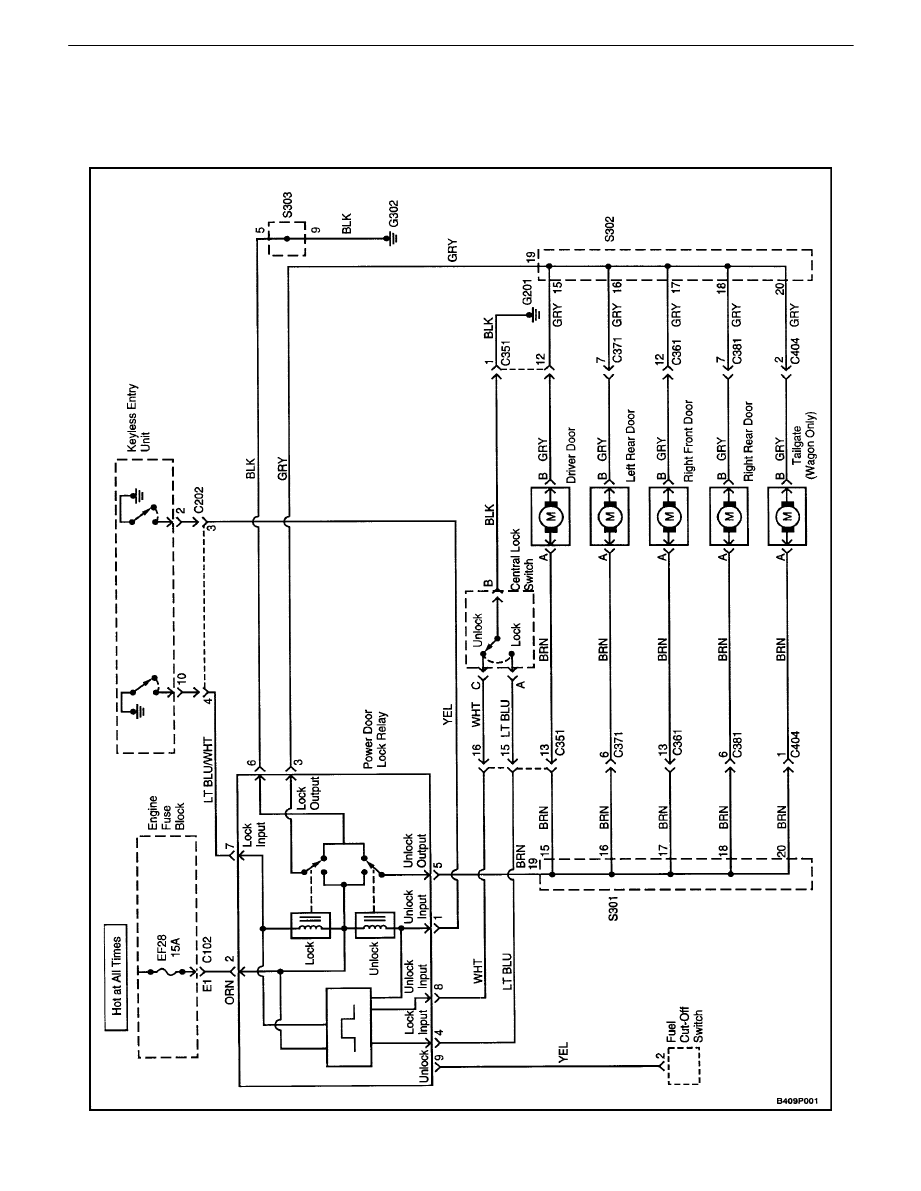
9P – 4

I

DOORS

DAEWOO V–121 BL4

POWER WINDOWS ((FRONT AND REAR))

DOORS  9P – 5

DAEWOO V–121 BL4

DIAGNOSIS

POWER DOOR LOCKS

Power Door Locks Do Not Operate At Any Door

Step

Action

Value(s)

Yes

No

1

Check fuse EF28.
Is fuse Ef28 blown ?

Go toStep 2

Go toStep 3

2

1.  Check for a short circuit and repair it, if neces-

sary.

2.  Replace fuse EF13.

Is the repair complete ?

System OK

3

Check the voltage at fuse EF28.
Is the voltage equal to the specified valus ?

11––14 v

Go toStep 5

Go toStep 4

4

Repair the power supply circuit for fuse EF28.
Is the repair complete ?

System OK

5

Check the voltage at the YEL wire of the power door
lock relay connector.
Is the voltage equal to the specified value ?

Go toStep 7

Go toStep 6

6

Repair the short to voltage between the power door
lock relay connector and the fuel cutoff switch.
Is the repair complete ?

System OK

7

Check the voltage at terminal 2 (ORN) of the power
door lock relay connector.
Is the voltage equal to the specified value ?

11––14 v

Go toStep 9

Go toStep 8

8

Repair the open circuit between fuse EF28 and ter-
minal 2 (ORN) of the door lock relay connecotor.
Is the repair complete ?

System OK

9

Use an ohmmeter to check the continuity between
terminal 6 (BLK) of the power door lock relay con-
nector and ground.
Is the continuity equal to the specified value ?

[

 0 

W

Go toStep 11

Go toStep 10

10

Repair the open circuit between terminal 6 (BLK) of
the power door lock relay connector and ground.
Is the repair complete ?

System OK

11

1.  Disconnect the power door lock relay connec-

tor.

2.  Connect a fused jumper wire to the positive

battery terminal.

3.  Connect another jumper wire to ground.
4.  Apply the positive jumper wire to terminal 3

(GRY) of the power door lock relay connector.

5.  Apply the grounded jumper wire to terminal.
6.  Switch the jumper wires so that the positive

jumper is connected to terminal 5 (BRN) and
the grounded jumper is connected to terminal 3
(GRY).

Do the doors lock and unlock when power and
ground are applied to terminals 3 and 5 of the door
lock relay connector ?

Go toStep 15

Go toStep 12

9P – 6

I

DOORS

DAEWOO V–121 BL4

Step

No

Yes

Value(s)

Action

12

Repair the open circuit between terminal 3 of the
power door lock relay and splice pack S302, or be-
tween terminal 5 of the door lock relay and splice
pack S301.
Is the repair complete ?

System OK

13

1.  Raise the power window in the driver

'

s side

door.

2.  Disconnect the central lock switch connector at

the top of the door lock. (There are three con-
nectors on the door lock. Use the schematic to
verify the correct connector.)

3.  Use an ohmmeter to check the continuity be-

tween terminal B (BLK) of the central lock
switch connector and ground.

Is the continuity equal to the specified value ?

[

 0 

W

Go toStep 15

Go toStep 14

14

Repair the open circuit between the central lock
switch connector terminal B (BLK) and ground.
Is the repair complete ?

System OK

15

1.  Make sure the lock relay connector is con-

nected.

2.  Touch a grounded jumper wire to terminal A

(LT BLU) of the disconnected central lock
switch connector.

3.  Remove the grounded jumper wire and touch it

to terminal C (WHT) of the disconnected cen-
tral lock switch connector.

Do the doors lock and unlock when terminals C and
A are alternately grounded ?

Go toStep 16

Go toStep 17

16

1.  Make sure all the lock rods are connected to

the driver

'

s side door lock.

2.  If no disconnected lock rods are found, replace

the driver

'

s side door lock with the integral door

lock switch. ( Do not confuse the door lock with
the lock cylinder. The door lock has three con-
nectors:the lock switch, the lock solenoid, and
the door contact switch. Use the schematic to
verify the correct connector.)

Is the repair complete ?

System OK

17

Use an ohmmeter to check the continuity between
terminal A (LT BLU) of the disconnected central lock
switch connector and terminal 4 (LT BLU) of the
power door lock relay connector.
Is the continuity equal to the specified value ?

[

 0 

W

Go toStep 19

Go toStep 18

18

Repair the open LT BLU wire.
Is the repair complete ?

System OK

19

Use an ohmmeter to check the continuity between
terminal C (WHT) of the disconnected central lock
switch connector and terminal 8 (WHT) of the door
lock relay connector.
Is the continuity equal to the specified value ?

[

 0 

W

Go toStep 21

Go toStep 20


Content   ..  20  21  22  23   ..