DAF CF65, CF75, CF85 Series . Manual - part 962


  Index      DAF     DAF CF65, CF75, CF85 Series - service repair manual


Search            


Content   ..  960  961  962  963   ..


DAF CF65, CF75, CF85 Series . Manual - part 962


©

 200423

3-5

Inspection and adjustment

STEERING BOX

ΧΦ65/75/85 series

7

3

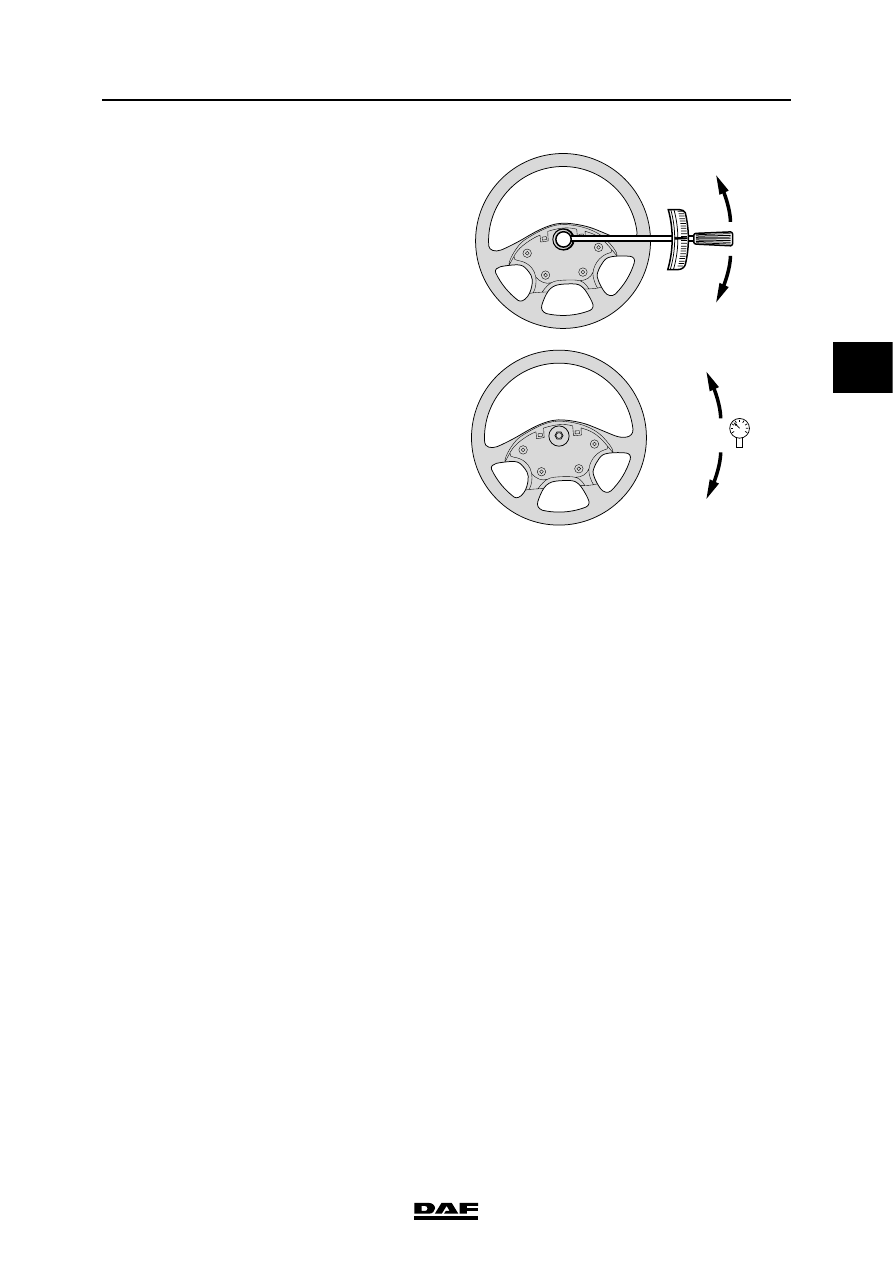
16. Turn the steering wheel fully left (RHD fully 

right) until the end stop is reached. Fit a 

torque wrench to the steering wheel nut and 

pull on the torque wrench with a tightening 

torque of 35 Nm. The maximum reading on 

the pressure gauge should be 80 bar.

This will correctly re-adjust the wheel 

deflection limiting valve, which has its end 

stop at the steering box cover.

17. Run the engine at idling speed and turn the 

steering wheel fully right (RHD fully left) until 

the end stop is reached. The pressure 

should not exceed approx. 100 bar; this 

pressure should not be continued for more 

than 5 seconds.

18. While the steering wheel is at its end stop, 

loosen the lock nut one turn and screw in the 

adjusting bolt, while securing the lock nut at 

the same time.

Screw in the adjusting bolt, until the pressure 

is reduced to a maximum of 80 bar. This will 

correctly re-adjust the wheel deflection 

limiting valve, which has its end stop against 

the adjusting bolt.

19. Set the engine speed to 1200 - 1400 rpm. 

The final limiting pressure should not exceed 

80 bar.

Screw the adjusting bolt in further if the 

pressure is too high.

Note:

Do not screw in the adjusting bolt further than 

is strictly required, as the other wheel 

deflection limiting valve could lose its 

previous setting in this way, in which case 

the adjusting procedure must be repeated 

from the start.

There is also the chance that the wheel 

deflection limiting valve will open too early, 

thus reducing the pressure too fast so that 

maximum wheel deflection is not reached.

20. Tighten the lock nut to the specified 

tightening torque. See 'Technical data'.

21. Turn the steering wheel fully left (RHD fully 

right) until the end stop is reached. Set the 

engine speed to 1200 - 1400 rpm and check 

the final limiting pressure.

LHD

RHD

35Nm

S7 00 562

RHD

LHD

max.
100 bar

S7 00 563

STEERING BOX

3-6

©

 200423

Inspection and adjustment

3

ΧΦ65/75/85 series

7

22. Measure the length of the part of the 

adjusting bolt that protrudes from the 

steering box (distance A in drawing). The 

total length (including the nut) should not 

exceed 26 mm.

If the adjusting bolt protrudes further from the 

steering box than the above-mentioned 

length, an adjusting bolt of the wrong length 

has been used or the wheel deflection 

limiting valves have been incorrectly set.

In that case, the total length of the adjusting 

bolt should be checked, and the adjusting 

procedure repeated.

The adjusting bolt should not 

protrude further from the steering 

box than is specified, in order to 

keep a sufficient screw thread length 

in the housing. A larger dimension 

could result in loss of the bolt and 

loss of steering power.

23. Remove the jack.

24. Remove the T-piece and the pressure 

gauge.

25. Fit the delivery line.

26. Check the steering oil level in the reservoir 

after connecting the pressure gauge and top 

up the oil if required.

27. Bleed the steering gear. To do so, run the 

engine at idling speed for approx. 2 minutes, 

without steering.

28. Retighten the steering wheel nut to the 

specified tightening torque. See 'Technical 

data'.

3

2

1

A

S7 00 045

}

©

 200423

3-7

Inspection and adjustment

STEERING BOX

ΧΦ65/75/85 series

7

3

3.2 INSPECTION AND ADJUSTMENT, PRESSURE POINT

Inspection of the pressure point
1.

Place the sector shaft in the central position, 

by aligning the markings on the sector shaft 

and on the steering box.

2.

Remove the steering rod from the pitman 

arm.

Note:

When a steering rod has been removed, the 

input shaft must not be rotated more than 

1.5 turns (counting from the central position) 

because otherwise the setting of the wheel-

deflection limiting valves will be changed.

3.

Check whether the sector shaft is still in the 

central position, using the markings.

4.

Take hold of the pitman arm and carefully 

move it in its direction of rotation to feel 

whether there is play. Make sure that the 

input shaft is not rotated more than 1.5 turns, 

counting from the central position.

There should be no play in the central 

position of the steering box. Outside the 

central position of the steering box, play is 

allowed.

5.

If play can be felt, this can be remedied using 

the adjusting bolt (1).

S7 00 024

S7 00 027

S7 00 593

1

2

STEERING BOX

3-8

©

 200423

Inspection and adjustment

3

ΧΦ65/75/85 series

7

Adjusting the pressure point
1.

Check whether the sector shaft is still in the 

central position, using the marks.

2.

Loosen the lock nut (2) one turn.

3.

Loosen the adjusting bolt (1) one turn until 

noticeable play can be felt.

4.

Slowly turn the adjusting bolt (1) to the right, 

until no play can be felt at the pitman arm. 

The torque used should not exceed 15 Nm.

5.

Turn the adjusting bolt another 

 to ∂ turn 

clockwise.

If the adjusting bolt is turned 

clockwise too far, the steering wheel 

will not return to its central position 

by itself after making a turn. The 

steering force at the central position 

will increase and the directional 

stability characteristics of the 

vehicle will deteriorate.

6.

Tighten the lock nut (2) to the specified 

tightening torque. See 'Technical data'. 

Make sure that the adjusting bolt (1) does not 

turn too.

7.

Check the pitman arm to see whether there 

is still play. You should not feel any play for a 

 of a turn to the left and right of the central 

position of the input shaft.

8.

If play can still be felt, the adjusting 

procedure should be repeated.

9.

Fit the steering rod on to the pitman arm.

10. Make a test run and check the vehicle's 

directional stability and check whether the 

steering wheel returns to the central position 

after taking a turn.

S7 00 024

S7 00 593

1

2

}


Content   ..  960  961  962  963   ..