DAF CF65, CF75, CF85 Series . Manual - part 929
©
200423
4-3
Disassembly and assembly
BRAKE SYSTEM AND COMPONENTS
ΧΦ65/75/85 series
6
5
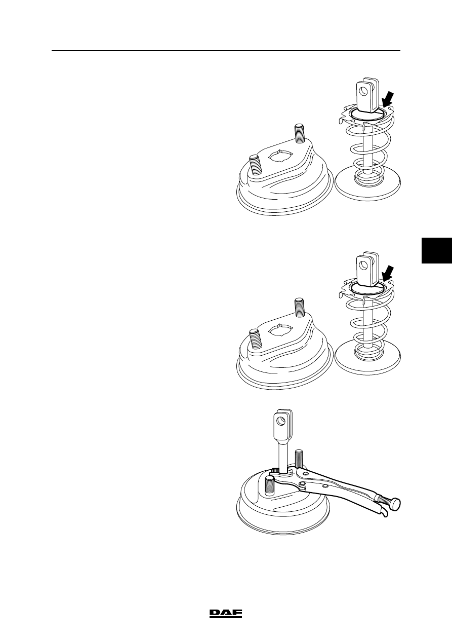
9.
Remove the split ring between fork and
spring retainer. The spring retainer
and spring can now be removed.
Assembly, brake chamber
1.
Apply pressure to connection point (12)
(min. 6.0 bar).
2.
Install the diaphragm.
3.
Place the spring and spring retainer on the
yoke, and fit the split ring.
4.
Place the front cover of the brake chamber
on the yoke and press the cover downwards
against the spring tension. Place a wrench
on the yoke rod at the assembly surface of
the brake chamber.
5.
Place the complete front cover on the brake
chamber and fit the clamping strap,
tightening it to the specified torque.
See "Technical data". Remove the wrench.
6.
Fit the flexible bleed pipe with the sinter filter
fitted at the brake chamber side. Ensure that
the filter is correctly mounted in the flexible
bleed pipe to prevent any dirt from entering
the spring brake section.
R600195
R600195
R600196