DAF CF65, CF75, CF85 Series . Manual - part 894
6
CF65/75/85 series
Description of components
OPERATION OF BRAKE COMPONENTS
2-11
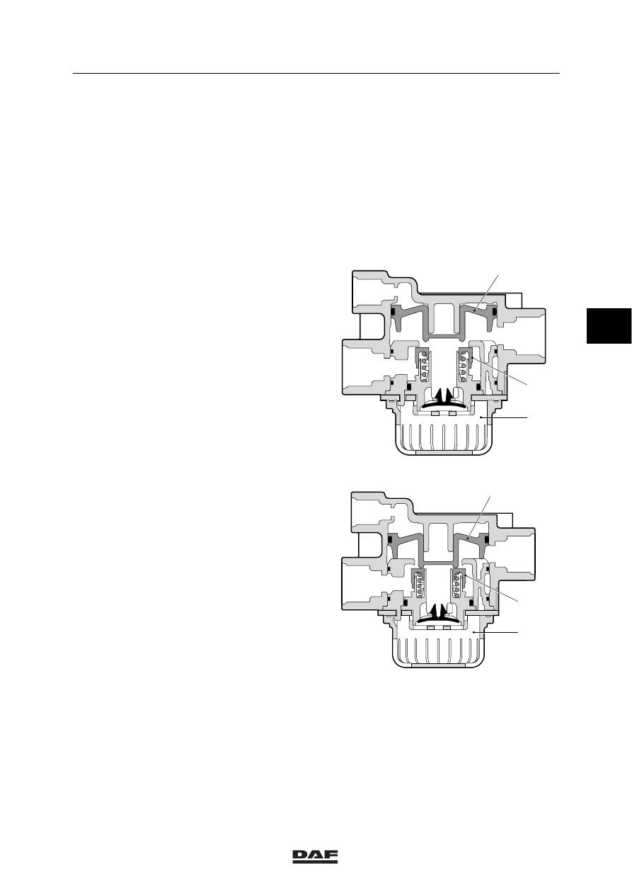
2.6 RELAY VALVE
Purpose
The purpose of the relay valve is to allow fast
aeration and venting of the spring brake
cylinders and brake cylinders, shortening the
brake reaction/release time.
Note:
The hysteresis of the relay valve used for the
parking brake is greater and therefore is not
suitable for use in the service brake.
The air reservoir is connected to connection
point 1. When connection point 4 is
pressureless, inlet 5 is closed and exhaust 6
opened. The brake chambers connected to
connection point 2 are now vented.
When compressed air passes through
connection point 4 into chamber ‘a’ above piston
7, the piston is forced downwards. Outlet 6 is
closed and inlet 5 opened. The compressed air
now passes from the air reservoir to the brake
chambers.
A state of balance is achieved when the
pressures on both sides of piston 7 are equal.
Then, both the outlet and the inlet are closed.
When the pressure in connection point 4 and
consequently in chamber ‘a’ drops, piston 7 is
forced upwards. Inlet 5 is closed and outlet 6
opened and as a consequence the brake
chambers are blown off through vent opening 3.
The rubber flap in opening 3 prevents dirt from
entering, whilst providing a large opening for air
to be blown off.
R600490
2
1
6
4
A
5
3
7
R600491
2
1
6
4
A
5
3
7
4
ᓻ 200324