DAF CF65, CF75, CF85 Series . Manual - part 502


  Index      DAF     DAF CF65, CF75, CF85 Series - service repair manual


Search            


Content   ..  500  501  502  503   ..


DAF CF65, CF75, CF85 Series . Manual - part 502


5

CF65/75/85 series ≥0E621376

Removal and installation

REPAIRING WIRING

2-3

The contacts may also be locked secondarily by

the lower part of the connector. After tilting this

lower part, the contacts can be removed by

unlocking the primary lock using the proper

ejector tool.

This type of lock is used only on 2-row

connectors.

Examples:

-

MTCO connector

E501497

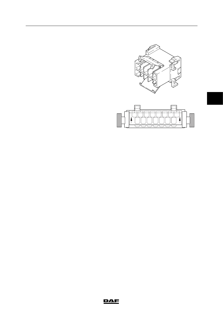
A different type of secondary lock is formed by

two sliding parts of the connector.

The upper half (on the wire insert side) and the

lower half form the extra contact lock.

To unlock this secondary contact lock the upper

half of the connector must be pushed away

slightly in the direction of the arrows on the

connector housing.

The contacts can then be removed from the

connector using the proper ejector tool.

After any installation of wires with contacts, the

connector must be pressed into the lock again. If

this is not done it will not fit into the counterpart.

Application examples:

-

Connector, CDS electronic unit

-

Connector, ECAS-2/3 electronic unit

-

Connector for UPEC electronic unit

E500475

15

8

14

7

13

6

12

5

11

4

10

3

9

2

1

15

8

14

7

13

6

12

5

11

4

10

3

9

2

1

3

 200404

5

REPAIRING WIRING

Removal and installation

CF65/75/85 series ≥0E621376

2-4

Ejecting contacts

For repair or extension of the wiring a contact

may have to be replaced or added. Using

special ejector tools a contact can be removed

from the connector without being damaged.

For the proper ejector tools, see ‘Parts Rapido’.

1. Push the wire with contact forwards (1). The

locking bolt (2) is now free from the

connector (3).

2. Push the proper ejector tool (4) into the

front of the connector. This will push the

locking bolt (2) down.

3. The contact can now be removed by gently

pulling the wire.

Note:

If the wire is pulled before the ejector tool

pushes the locking bolt down, the contact will

only be fixed in the connector even more.

E501482

1

2

4

3

Contacts are also used in which the locking bolt

(2) is on the rear of the connector (3).

1. Pull the wire and contact backwards (1).

The locking bolt (2) is now free from the

connector (3).

2. Push the proper ejector tool (4) into the

back of the connector. This will push the

locking bolt (2) up.

3. The contact can now be removed by gently

pushing the wire forwards.

Note:

Here the locking bolt works exactly the opposite

to the usual connectors.

Application examples:

-

EMAS pressure sensor connector

-

Accelerator sensor connector, CF series /

XF series

For each contact a specific ejector tool is

required.

The proper ejector tool for each contact can be

found through ‘Parts Rapido’.

E501696

1

4

2

3

3

 200404

5

CF65/75/85 series ≥0E621376

Removal and installation

REPAIRING WIRING

2-5

An MQS (Micro Quadlock System) contact

lock

Before the contact can be removed, the lock

must be unlocked with a needle-shaped object.

1. First press the lock at the end of the

connector (1). At the same time gently pull

the wire (2) until resistance is felt.

2. Then press the second lock (3) and again

gently pull the wire (2).

3. The contact can now be removed from the

connector.

Note:

This type of contact is locked twice and must

therefore be unlocked twice.

Application examples:

-

Connector for VIC electronic unit

E501486

1

3

2

Removing contacts from the Bosch 89-pin

connector

To remove a contact from this connector

proceed as follows:

1. Fold the protective cover around the wiring

harness down by pushing the lock

outwards.

2. Now push the two outer halves of the

protective cover outwards and then

upwards. The protective cover can now be

removed.

3. The pink secondary contact lock (1) must

be slid to the centre of the connector to

enable the contacts to be removed.

4. The contacts can now be removed using

the proper ejection tool.

Note:

The larger contacts are locked with four locking

bolts. The smaller contacts are locked with two

locking bolts.

Always unlock the locks when adding contacts!

E501485

1

3

 200404

5

REPAIRING WIRING

Removal and installation

CF65/75/85 series ≥0E621376

2-6

Fitting the Bosch 89-pin connector

When refitting the protective cover, ensure that

the siphon and slide are both in the ‘unlocked’

position.

If they are not, the connector, when fitted, will

not be locked correctly on the electronic unit. As

a result, the contact between the connector and

the electronic unit may be bad.

Application examples:

-

Connector, ECS-DC3 electronic unit

E501498

Removing 39-pin connector contacts

1. Loosen union G.

2. Push pressure ring H and seal K back

slightly over the wiring.

3. Then eject the contacts from connector

housing F using a special ejector tool from

contact kit A or B.

Fitting 39-pin connector contacts

1. Fit union G, pressure ring H over the wiring.

2. Fit new contacts to the wires using the

correct tool.

3. Insert the wires and contacts through

seal K.

4. Press the contacts to their definitive

positions in connector housing F.

5. Press seal K against connector housing F.

6. Position pressure ring H so that the two

ridges on the side of connector housing F

fall into the pressure ring recesses.

7. Tighten union G by hand.

Note:

-

Pressure ring H has contact numbers (their

purpose is to enable the contacts to be

positioned correctly). These contact

numbers must be in the same position as

the contact numbers on the connector

housing.

-

When an incorrectly positioned wire is

removed the seal will leak. If a new wire is

not inserted a sealing plug should be fitted.

E500477

G

H

K

F

3

 200404


Content   ..  500  501  502  503   ..