DAF CF65, CF75, CF85 Series . Manual - part 495


  Index      DAF     DAF CF65, CF75, CF85 Series - service repair manual


Search            


Content   ..  493  494  495  496   ..


DAF CF65, CF75, CF85 Series . Manual - part 495


5

CF65/75/85 series ≥0E621376

General

COMPONENTS

1-1

1. GENERAL

1.1 MULTIMETER

Various measurement options can be selected

on the Fluke 87 multimeter.

Units of measurement

The multimeter should be set to the range for

the unit of measurement required.

For example, voltage range, current range, or

resistance range.

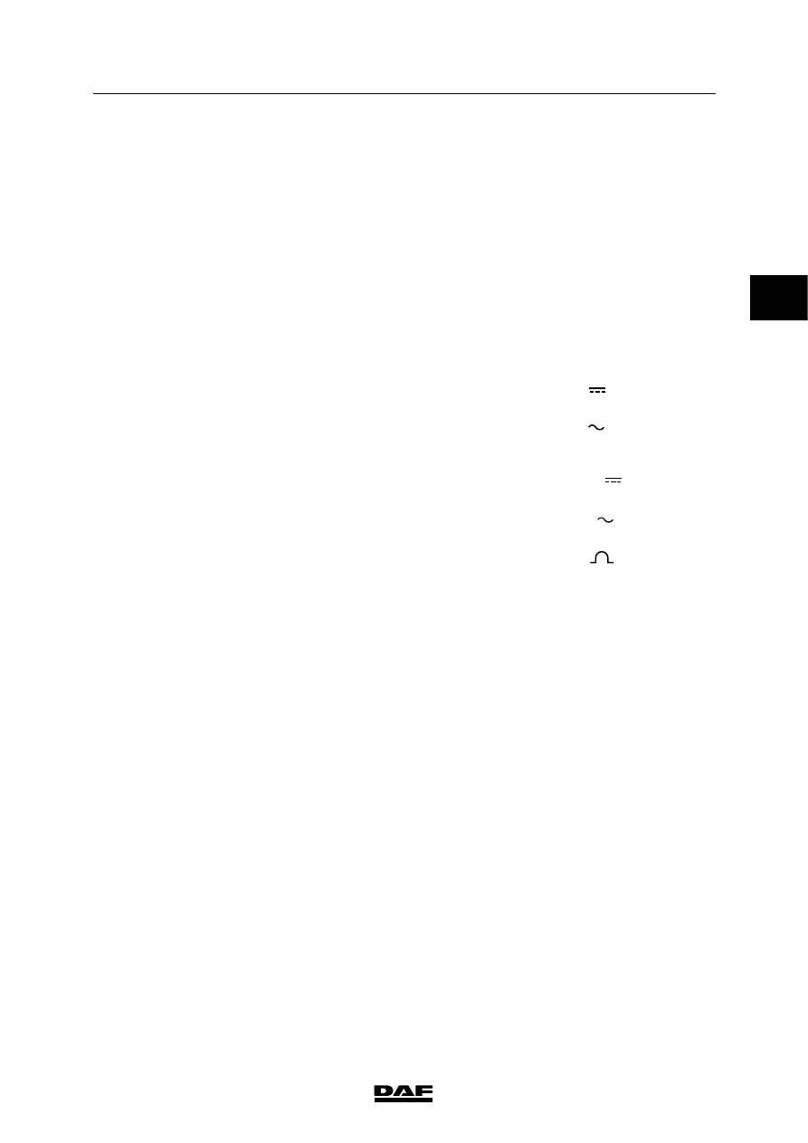
The units of measurement are indicated by

symbols on the meter. The following symbols

are used:

1.

DC voltage

2.

AC voltage

3.

DC current

4.

AC current

5.

Resistance

6.

Duty cycle

7.

Frequency

DCV - V 

ACV - V

DCA - A   

ACA -A

Ohm - 

%

Hz 

1

2

3

4

5

6

7

W 5 01 004

2

 200404

5

COMPONENTS

General

CF65/75/85 series ≥0E621376

1-2

1.2 SCOPEMETER

Diagnostics in modern electronic systems is

becoming steadily more complex.

Using a multimeter on its own is not always

sufficient to diagnose a fault.

The scopemeter allows complex signals to be

measured.

Practical examples of complex signals are:

-

PWM signals

-

signal deformation

-

CAN-bus-signals

2

 200404

5

CF65/75/85 series ≥0E621376

General

COMPONENTS

1-3

1.3 SIGNAL MEASUREMENTS

Sine--wave signal (AC voltage)

This signal changes polarity regularly in relation

to the “0” line.

Frequency

The frequency is shown in Hertz (Hz).

The number of complete sines per second is the

frequency of the signal (3 Hz in the diagram).

Voltage

If the number of sines per second increases, not

just the frequency increases but also the

voltage.

Measuring a sine wave signal

The sine wave signal can be measured in the

following ways using a multimeter:

-

Multimeter in the frequency position (Hz).

This measures the number of complete

sines per second.

-

Multimeter in the AC voltage position.

This measures the average value of the

supplied voltage.

Sine wave signals in the vehicle

-

Wheel speed sensor output signal.

-

Engine speed sensor output signal.

+

-

+

-

t

1

2

3

+

-

W 5 01 002

0

0

0

2

 200404

5

COMPONENTS

General

CF65/75/85 series ≥0E621376

1-4

Square wave signals

Square wave signals are signals with only two

voltage levels, both of which have the same

duration in principle (t1 is equal to t2).

If there is a difference between the duration for

the two levels (t1 is not equal to t2), the signal is

also called a ”pulse train“.

Duty cycle

The duty cycle is the ratio between the two

voltage levels, expressed as a percentage.

A

x 100%

B

The voltage level ratio of a “pulse train” may

change (for example, when the vehicle speed

increases).

If the number of pulses per unit of time

increases, the duty cycle reading will rise.

Voltage

An increase in the number of pulses per unit of

time will not only lead to a higher duty cycle ratio

but also to a higher mean voltage.

+

0

t

2

t

1

t

2

0

+

A

B

0

+

t

1

0

+

A

B

W 5 01 001   

2

 200404


Content   ..  493  494  495  496   ..