DAF CF65, CF75, CF85 Series . Manual - part 370


  Index      DAF     DAF CF65, CF75, CF85 Series - service repair manual


Search            


Content   ..  368  369  370  371   ..


DAF CF65, CF75, CF85 Series . Manual - part 370


3

CF65/75/85 series

Removal and installation

ZF INTARDER

4-3

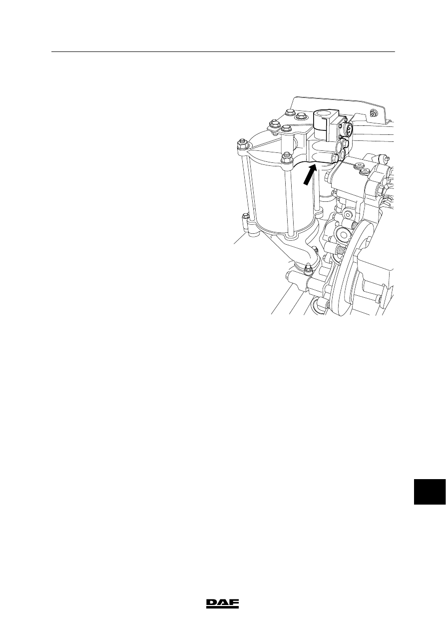
4.2 REMOVAL AND INSTALLATION, AIR SUPPLY SOLENOID VALVE

Removing the air supply solenoid valve
1.

Remove the air pipe from the solenoid
valve.

2.

Remove the electric wiring from the
solenoid valve.

3.

Remove the attachment bolts from the
solenoid valve and remove the solenoid
valve.

4.

Remove the O-ring.

Installation, air supply solenoid valve
1.

Fit a new O-ring in the slot on the solenoid
valve.

2.

Install the solenoid valve.

3.

Connect the electrical wiring to the solenoid
valve.

4.

Connect the air pipe to the solenoid valve.

V300446

12

ᓻ 200337

3

ZF INTARDER

Removal and installation

CF65/75/85 series

4-4

4.3 REMOVAL AND INSTALLATION, ACCUMULATOR

To prevent skin injury, avoid
unnecessary contact with the
drained oil.
In the course of the following
operations, oil and water will
escape from the heat exchanger.
Collect the oil and water.
To prevent skin injury, avoid
unnecessary contact with the
drained oil.

Removing the accumulator
1.

Drain as much coolant and oil as necessary.

2.

Disconnect the water hose from the
left-hand side of the heat exchanger.

3.

Remove the air pipe from the solenoid
valve.

4.

Remove the electrical wiring from the
solenoid valve.

5.

Remove the attachment bolt from the water
pipe bracket and the attachment bolts on
top of the accumulator bracket.

6.

Take out the bolts attaching the accumulator
to the heat exchanger and remove the
accumulator.

Installing the accumulator
1.

Fit new O-rings on the accumulator bracket
and install the accumulator on the heat
exchanger.

2.

Install the accumulator bracket attachment
bolts at the top.

3.

Fit the water pipe bracket attachment bolt.

4.

Install the solenoid valve.

5.

Connect the air pipe to the solenoid valve.

6.

Connect the electrical wiring to the solenoid
valve.

7.

Install the water hose at the left-hand side.

8.

Fill the cooling system.

9.

Fill the gearbox with oil. Check the oil level
in the gearbox. See “Inspection and
adjustment”.

V300447

12

ᓻ 200337

3

CF65/75/85 series

Removal and installation

ZF INTARDER

4-5

4.4 REMOVAL AND INSTALLATION, HEAT EXCHANGER

In the course of the following
operations, oil and water will
escape from the heat exchanger.
Collect the oil and water. Take
measures to prevent the heat
exchanger from falling down.

Removing the heat exchanger
1.

Drain as much coolant and oil as necessary.

2.

Remove the water hoses from the heat
exchanger.

3.

Remove the air pipe from the solenoid
valve.

4.

Remove all electrical wiring from the
intarder.

5.

Remove the attachment nuts from the studs
attaching the heat exchanger to the
hydraulic control unit.

6.

Remove an attachment bolt from the heat
exchanger oil connection flange attached to
the rear cover of the gearbox.

7.

Remove the heat exchanger together with
the accumulator.

8.

Remove the two O-rings for the oil ducts of
the heat exchanger from the control unit.

9.

If necessary, remove the accumulator and
the solenoid valve.

10. If the heat exchanger displays any leaks, it

must be replaced, as it cannot be repaired.

V300448

V300195

12

ᓻ 200337

3

ZF INTARDER

Removal and installation

CF65/75/85 series

4-6

Installing the heat exchanger
1.

Insert new O-rings into the circular slots of
the control unit.

2.

Install the studs in the heat exchanger and
tighten them to the specified torque. See
“Technical data”.

3.

Apply Loctite to the contact surfaces, studs,
and attachment nuts/bolt. See “Technical
data”.

4.

Install the heat exchanger on the control
unit and tighten the attachment nuts to the
specified torque. See “Technical data”.

5.

Install the heat exchanger oil connection
flange attachment bolt which is attached to
the rear cover of the gearbox, and tighten to
the specified torque. See “Technical data”.

6.

Connect the water hoses to the heat
exchanger.

7.

Connect the air pipe to the solenoid valve.

8.

Connect the electrical wiring to the intarder.

9.

Fill the cooling system.

10. Fill the gearbox with oil.

11. Check the oil level in the gearbox. See

“Inspection and adjustment”.

V300195

V300448

12

ᓻ 200337


Content   ..  368  369  370  371   ..