DAF CF65, CF75, CF85 Series . Manual - part 311
3
CF65/75/85 series
General
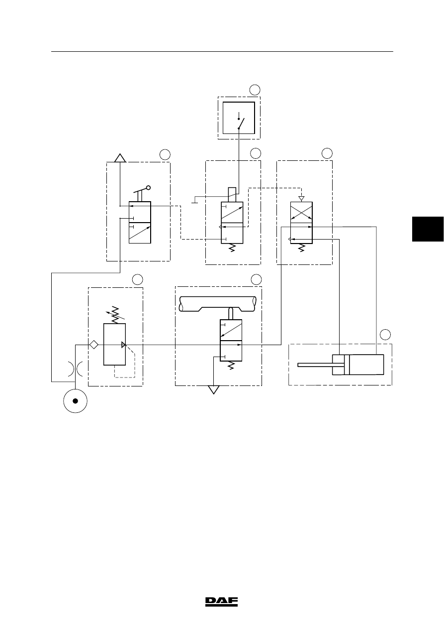
GEARBOX - PNEUMATIC SECTION
1-27
Pneumatic diagram, Eaton FS/6309A
N
V
1
1
21
GP
H
L
H
L
4
1
21
22
V300454
1
7
5
4
3
6
2
+
4
ᓻ 200337
|
|
|
3 CF65/75/85 series General GEARBOX - PNEUMATIC SECTION 1-27 Pneumatic diagram, Eaton FS/6309A N V 1 1 21 GP H L H L 4 1 21 22 V300454 1 7 5 4 3 6 2 + 4 ᓻ 200337 |