DAF CF65, CF75, CF85 Series . Manual - part 1129


  Index      DAF     DAF CF65, CF75, CF85 Series - service repair manual


Search            


Content   ..  1127  1128  1129  1130   ..


DAF CF65, CF75, CF85 Series . Manual - part 1129


©

 200518

3-25

Inspection and adjustment

EXPLANATORY NOTES ON THE MAINTENANCE ACTIVITIES

ΧΦ65/65 (II) series

5

3.26 INSPECTION AND ADJUSTMENT, LOAD-DEPENDENT CONTROL VALVE, 

LEAF SUSPENSION

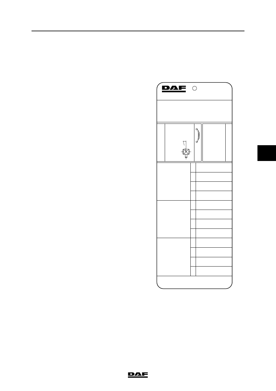
Explanatory notes on instruction plate 
for CF65

This plate is mounted on the rear door pillar of the 

vehicle. The data on axle loads and delivery 

pressures are listed on the instruction plate in the 

sequence of the axles beneath the vehicle. 

"1" refers to the (first) front axle, "2" to the 

following axle, etc.

If the vehicle is fitted with a relay valve in the front 

axle brake circuit, the box beneath the valve 

illustration will be blank. Throughout the column, 

a value of 8.1 bar has been filled in for "delivery 

pressure p2" under axle "1".

If the vehicle is equipped with a control valve 

instead of the relay valve mentioned, the box will 

contain a pressure ratio, e.g. "i = 1 : 1.5". The 

"delivery pressure p2" of axle "1" then indicates 

variable readings.

These values can be used to check the brake 

pressure values of the front axle and to carry out 

the inspection/adjustment below at the same 

time. To do this, connect a pressure gauge to the 

test connection of one of the front axle brake 

cylinders.

AUTOM. LASTAFHANKELIJKE REMKRACHTREGELING
AUTOM. LOAD SENSING DEVICE
AUTOM. LASTABHAENGIGE BREMSKRAFT REGELEINR.
DISPOSITIF DE CORRECTION AUTOM. DE FREINAGE
REGOLATORE AUTOM. DELLA FORZA FRENANTE
REGULADOR AUTOM. DEL ESFUERZO DE FRENANDA

TYPE   -  TIPO   :   FA

1425287

2

1.8

2.0

3.0

4.0

8.0

10.0

11.5

13.0

2

1.8

1.8

2.2

3.1

6.4

7.6

8.2

8.2

1

5.7

5.7

5.8

6.1

7.4

7.8

8.0

8.0

1

ASLAST                          G

AXLE LOAD

ACHSLAST

CHARGE SOUS ESSIEU

CARICO ASSE

CARGA EJE


x10

4

 N

UITGESTUURDE DRUK   p2

DELIVER

Y PRESSURE

AUSGESTEUER

TER DRUCK

PRESSION DELIVREE

PRESSIONE USCIT

A

PRESION DE SALIDA

                 bar

BALG DRUK                     p3

PRESSURE BELLOWS

BALG DRUCK

PRESSION COUSSIN

PRESS. CUSCINI ARIA

PRESION FUELLES

                  bar

±0.4

±0.2

W475 721 004 0

1396041

i  =  1  :  1.5

MEEREGEL

VENTIEL

EMPTY

-LOAD V

A

LV

E

LAST

-LEER VENTIEL 

V

A

LVE CHARGE-VIDE

V

A

LVOLA VUOTO-CARICO

V

A

LVULA V

ACIO-CARGA

p1 = > 8.5 bar

p4 = 8.0 bar

L = 140 mm

a = 15  ±2 

G=11.0

L

p1

p2

p4

R600479

EXPLANATORY NOTES ON THE MAINTENANCE ACTIVITIES

3-26

©

 200518

Inspection and adjustment

5

ΧΦ65/65 (II) series

Explanatory notes on instruction plate for 
CF65 (II)

This plate is mounted on the rear door pillar of the 

vehicle. The data relating to axle loads and output 

pressures are listed on the instruction plate 

following the sequence of the axles beneath the 

vehicle.

So "1" is the front axle and "2" the rear axle. 

"G" stands for the load in kg.

These values can be used to check the brake 

pressure values of the front axle and to carry out 

the inspection/adjustment below at the same 

time. To do this, connect a pressure gauge to the 

test connection of one of the front axle brake 

cylinders.

Inspection and adjustment, load-dependent 
control valve, leaf suspension
1.

Measure the weight plus load of the rear 

axle(s).

2.

Check the attachment of the control lever 

and its ease of operation.

3.

Check whether the correct valve and the 

correct springs have been fitted (for 

information, see the instruction plate).

4.

Check the length of the control lever 

(see "L" on the instruction plate).

5.

Connect pressure gauge (4) to the test 

connection close to connecting point 

 on 

the load-dependent control valve (input 

pressure).

6.

Connect pressure gauge (2) to the test 

connection on one of the brake cylinders 

(service brake connection) of the rear axle.

7.

Make sure that the reservoir pressure is 

higher than 8.5 bar throughout the testing 

process.

8.

Depress the brake pedal until the pressure 

gauge (4) indicates a value of 8 bar.

R600944

1/4

4

2

2

R600562

1

©

 200518

3-27

Inspection and adjustment

EXPLANATORY NOTES ON THE MAINTENANCE ACTIVITIES

ΧΦ65/65 (II) series

5

9.

Read the brake pressure of the rear axle 

from pressure gauge 2 and check that this 

value matches the one listed on the 

instruction plate in the table under "output 

pressure p2" to the rear axle.

10. Correct, if necessary, the brake pressure by 

moving the rubber sleeve (1) in relation to the 

vertical connecting rod. On no account 

change the length L of the (horizontal) 

control lever.

11. Remove the rubber sleeve (2) and move the 

control lever towards maximum load. Check 

that the output pressure is now allowed 

through (almost) without reduction.

Note:

The small socket head screw in the centre of the 

valve must not be adjusted.

Drive and chassis

L

R600781

1

2

EXPLANATORY NOTES ON THE MAINTENANCE ACTIVITIES

3-28

©

 200518

Inspection and adjustment

5

ΧΦ65/65 (II) series

3.27 CHECKING THE DIFFERENTIAL FOR LEAKS

1.

Visually inspect the differential for leaks. 

3.28 CHECKING THE OPERATION OF THE DIFFERENTIAL LOCK

1.

Jack up the rear axle and support the axle on 

stands.

2.

Bring the air system to operating pressure.

3.

Engage the differential lock. The warning 

indicator should now be active.

4.

Check that there is a "rigid" connection 

between the driven wheels.

5.

Disengage the differential lock. The warning 

light should now go out and the "rigid" 

connection between the driven wheels 

should be broken.


Content   ..  1127  1128  1129  1130   ..