DAF XF105. Manual - part 99
 

  Index      DAF     DAF XF105 - service repair manual


Search            


Content   ..  97  98  99  100   ..


DAF XF105. Manual - part 99


1

©

 200528

3-15

Control functions

DMCI ENGINE MANAGEMENT SYSTEM

XF105 series

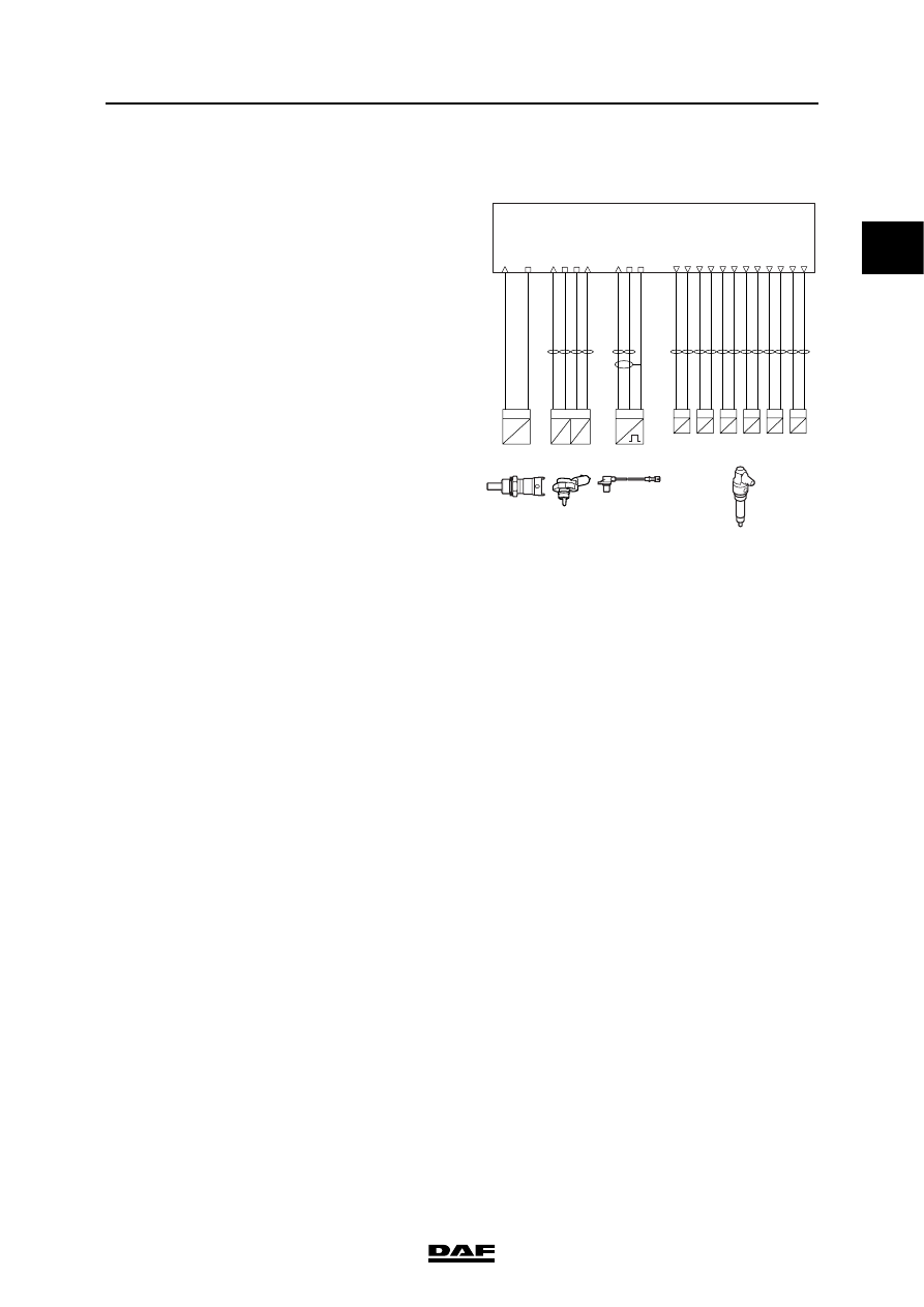
3.7 INJECTION TIMING CONTROL

The injection timing is calculated for the various 

different system statuses (starting, idling, part/full 

load, cruise and PTO). During each system 

status, the inlet air temperature (F649), the 

coolant temperature (F566), the engine speed 

(F552) and the calculated required quantity of 

fuel are taken into account as well.

The inlet air and coolant temperature are used to 

ensure that the emission of white smoke is kept 

within the limits. If the air intake temperature or 

the coolant temperature is lower then the 

injection timing will be earlier.

The moment at which the injector is controlled 

determines the injection timing.

Relevant components
-

Coolant temperature sensor (F566)

-

Charge boost pressure and temperature 

sensor (F649)

-

Crankshaft sensor (F552)

-

Injectors (B421 to B426)

i401014

D965

1 2

high-side

low-side

Cyl.6

B426

1 2

high-side

low-side

Cyl.5

B425

1 2

high-side

low-side

Cyl.4

B424

1 2

high-side

low-side

Cyl.3

B423

1 2

high-side

low-side

Cyl.2

B422

1 2

high-side

low-side

Cyl.1

Injectors

B421

temp.

F649

T

R

P

U

2 1

signal

ground

3 4

supply  5V

signal

shield

inlet

pres.

boost

ground

T

R

1

signal

2

F566

temp.

coolant

N

2 1

signal

return

3

F552

speed

crankshaft

A2

A8

A9

A22

A21

A14

A5

A18

A13

A1

A10

A17

C26

A34

C25

A27

A28

A30

A49

A50

A60

1

DMCI ENGINE MANAGEMENT SYSTEM

3-16

©

 200528

Control functions

XF105 series

3.8 IDLING CONTROL

The idling control ensures that the engine runs at 

a stable speed depending on the coolant 

temperature and the load on the engine.

If the signal from the accelerator pedal sensor is 

incorrectly received or is not received, the 

electronic unit increases the speed (1000 

rev

/

min

). 

This is to ensure that the vehicle can still be 

driven to a workshop or a safe place.

Relevant components

-

Coolant temperature sensor (F566)

-

Crankshaft sensor (F552)

-

Accelerator pedal sensor (F672)

i400997

D965

kl.30

shield

ground

T

R

1

signal

2

F566

temp.

coolant

Main
relay

Accelerator

Pedal  Sensor

G126

E118
(15A)

N

2 1

return

3

F552

speed

crankshaft

C26

C25

A49

A50

A60

B2

supply

supply

supply

ground

signal

supply 5V

ground

signal

C60

C61

C62

87 86

85

30

87a

B A

C D F

F672

B37

B33

B34

B38

B41

1

©

 200528

3-17

Control functions

DMCI ENGINE MANAGEMENT SYSTEM

XF105 series

3.9  TURBOCHARGER PRESSURE CONTROL

A waste gate is used to allow the exhaust gas 

flow to bypass the turbine, which reduces the 

drive of the turbocharger. Controlling the drive of 

the turbocharger, i.e. the exhaust gas flow, also 

controls the inlet air pressure. A conventional 

waste gate is adjusted so that it opens at a 

specific inlet air boost pressure. This is to protect 

the engine and the turbocharger against 

excessive loads. The application of an electronic 

control on this waste gate allows the inlet air 

pressure to be controlled precisely. For instance, 

in order to prevent too high a speed of the 

turbocharger it is possible to realise a relatively 

high boost pressure at a low speed and a 

relatively low boost pressure with high speeds. 

The waste gate is operated by a waste gate valve 

(B368). This valve is controlled by a duty cycle 

from pin C8 (10% is closed, 90% is fully open). 

The electronic unit calculates the required inlet air 

pressure depending on engine speed (F552), 

inlet air pressure (F649, pin A34), inlet air 

temperature (F649, pin A30), ambient air 

pressure (internal atmospheric pressure sensor) 

and the calculated fuel quantity.

i400998

D965

temp.

F649

T

R

P

U

2 1

signal

ground

ground

3 4

supply  5V

signal

shield

inlet

pres.

boost

2

B368

valve.

waste gate

1

2

signal

3

supply

supply

supply

C60

C61

C62

E184
(10A)

N

2 1

signal

return

3

F552

speed

crankshaft

A34

C59

C8

A27

A28

A30

A49

A50

A60

1

DMCI ENGINE MANAGEMENT SYSTEM

3-18

©

 200528

Control functions

XF105 series

The air supply for the waste gate valve comes 

from air circuit 4 and is adjusted in the valve from 

10 bar up to a specific control pressure 

depending on the duty cycle.

The electronic unit sends a duty cycle (PWM) 

signal to the internal electronics (A) of the waste 

gate valve. This signal reflects the requirements 

of the electronic unit. The waste gate valve also 

has an internal pressure sensor (C). This sensor 

measures the actual output pressure (2) to the 

waste gate. The sensor sends a signal to the 

internal electronics (A) of the waste gate valve. If 

the actual pressure measured differs at all from 

the requirement, the electronics (B) correct the 

duty cycle (PWM) to valve (D) so that the output 

pressure reaches the required value.

If the inlet air boost pressure and temperature 

sensor (F649) is defective, the waste gate valve 

is moved to a specific fixed "safe" position. The 

maximum boost pressure will not be reached in 

this situation.

Relevant components

-

Charge boost pressure and temperature 

sensor (F649)

-

Internal atmospheric air pressure sensor

-

Crankshaft sensor (F552)

-

Waste gate valve (B368)

U

PI

I

U

P

C

B

A

24V

GND

PWM

PWM

D

1

2

3

i400748

U

PI

I

U

P

C

B

A

24V

GND

PWM

PWM

D

1

2

3

i400748


Content   ..  97  98  99  100   ..