DAF LF45, LF55 Series. Manual - part 647
 

  Index      DAF     DAF LF45, LF55 Series - service repair manual


Search            


Content   ..  645  646  647  648   ..


DAF LF45, LF55 Series. Manual - part 647


©

 200515

3-17

Inspection and adjustment

EXPLANATORY NOTES ON THE MAINTENANCE ACTIVITIES

ΛΦ45/55 series

5

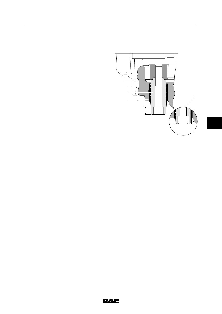
3.24 CHECKING THE BRAKE PAD THICKNESS AND BRAKE DISC

Version: Knorr SB 7000
1.

Check whether guide bush (4) protrudes 

from guide sleeve (6) (C).

If the guide bush (4) is level with the guide 

sleeve (6) (see detail A) the brake pad and 

brake disc thicknesses should be checked.

C

1

4

6

R600481

A

EXPLANATORY NOTES ON THE MAINTENANCE ACTIVITIES

3-18

©

 200515

Inspection and adjustment

5

ΛΦ45/55 series

Version: Knorr SN 7000
1.

Check the transition between the ribbed part 

of the rubber cover and the smooth part (A). 

If the smooth part is rolled inwards, the brake 

pad and brake disc thicknesses must be 

checked.

Version: Wabco
1.

There is no wear indicator in this version. 

The brake pad thickness must be inspected 

by using a mirror and a lamp, if necessary.

A

A

A

R600730

©

 200515

3-19

Inspection and adjustment

EXPLANATORY NOTES ON THE MAINTENANCE ACTIVITIES

ΛΦ45/55 series

5

3.25 INSPECTION AND ADJUSTMENT, LOAD SENSING VALVE, AIR 

SUSPENSION

Explanatory notes on instruction plate

The information contained on the plate relates to 

the axle loads, the output pressures and bellows 

pressures, in accordance with the order of axles 

beneath the vehicle.

"1" refers to the (first) front axle, "2" to the 

following axle, etc.

In the entire column, a reading of 6 bar has been 

filled in under "1".

If the vehicle is equipped with an empty/load 

valve, a pressure ratio is entered in the box under 

the valve illustration, e.g. "i = 1 : 1.5". 

The "delivery pressure p2" of axle "1" then 

indicates variable readings.

These values can be used to check the brake 

pressure values of the front axle and to carry out 

the inspection/adjustment below at the same 

time. To do this, connect a pressure gauge to the 

test connection of one of the front axle brake 

cylinders.

Inspection/adjustment
1.

Check that the correct valve has been fitted 

(see instruction plate).

2.

Connect pressure gauge (4) to the test 

connection close to connecting point 1/4 on 

the load sensing valve (input pressure).

3.

Connect pressure gauge (2) to the test 

connection on one of the brake cylinders 

(service brake connection) of the rear axle.

4.

Connect a pressure gauge (43) with a 

pressure-reducing valve to the simulation 

connection near connections 41 and 42 of 

the load sensing valve (= simulated 

adjustable bellows pressure).

5.

Make sure that the reservoir pressure is 

higher than 6.5 bar throughout the testing 

process.

6.

Set the simulated bellows pressure to its 

second lowest value, as indicated on the 

instruction plate.

7.

Depress the brake pedal until the pressure 

gauge (4) indicates a pressure of 6 bar.

R6 00 548

43

1/4

4

2

2

R600473

1

41 42

r

s

EXPLANATORY NOTES ON THE MAINTENANCE ACTIVITIES

3-20

©

 200515

Inspection and adjustment

5

ΛΦ45/55 series

8.

Read the brake pressure of the rear axle on 

pressure gauge 2 and check that this brake 

pressure matches the one listed on the 

instruction plate in the table under "output 

pressure p2" to the rear axle.

9.

If the measured value is not correct, 

depressurise connection (43) and, using a 

special slotted-nut spanner, special tool 

(DAF no. 1329464), turn the adjusting 

nut (s):

-

brake pressure too high: unscrew the 

adjusting nut

-

brake pressure too low: screw in the 

adjusting nut

Note:

When depressurising the simulation 

connection (pressure gauge 43), the air hose 

must remain connected to prevent the 

(actual) bellows pressure from accidentally 

activating the valve.

The small socket head screw in the centre of 

the valve must not be adjusted.

10. Repeat the procedure described in point 6 

until the measured brake pressure value is 

within the tolerance limits.

11. Set the simulated bellows pressure to its 

second highest value, as indicated on the 

instruction plate.

12. Depress the brake pedal until the pressure 

gauge (4) indicates a pressure of 6 bar.

13. Read pressure gauge (2) and check that this 

brake pressure matches the pressure 

indicated in the table on the instruction plate.

14. If the measured reading is not correct, 

depressurise connection (43) and turn 

adjusting bolt (r) using a Torx screwdriver:

-

brake pressure too high: screw in the 

adjusting bolt

-

brake pressure too low: unscrew the 

adjusting bolt

Note:

When depressurising the simulation 

connection (pressure gauge 43), the air hose 

must remain connected to prevent the 

(actual) bellows pressure from accidentally 

activating the valve.

The small socket head screw in the centre of 

the valve must not be adjusted.

15. If the adjusting bolt (r) has been turned, 

repeat the procedure from point 6.

R600478

43

1/4

4

2

2

R600473

1

41 42

r

s


Content   ..  645  646  647  648   ..