DAF LF45, LF55 Series. Manual - part 467
 

  Index      DAF     DAF LF45, LF55 Series - service repair manual


Search            


Content   ..  465  466  467  468   ..


DAF LF45, LF55 Series. Manual - part 467


©

 200436

3-19

Removal and installation

BRAKE SYSTEM AND COMPONENTS

ΛΦ45/55 series

6

4

3.

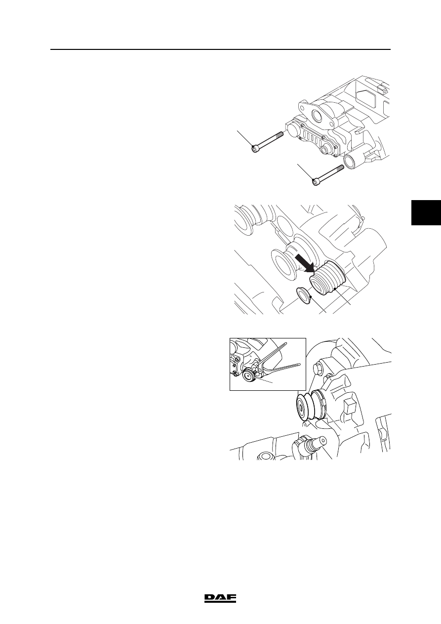
Fit the two Allen screws (2 and 3) and tighten 

them to the specified torque. See "Technical 

data". Do not re-use these screws. Always 

use new screws which have locking 

compound applied.

4.

Check that the brake calliper can move 

freely.

5.

Check that the bellows (5) and the ring (4) of 

the guide bush are properly in place on the 

inside of the brake calliper.

6.

Check that the automatic adjustment is 

working properly.

7.

Fit the bellows (10) and clamping strap (31). 

Check the bellows for proper sealing.

8.

Fit the brake pads.

9.

Fit the plug for the brake pad wear indicator.

10. Fit the brake cylinder.

2

3

R600720

R600721

5

4

39

31

R600467

31

BRAKE SYSTEM AND COMPONENTS

3-20

©

 200436

Removal and installation

4

ΛΦ45/55 series

6

3.13 REMOVAL AND INSTALLATION, BRAKE CALLIPER, KNORR SN7000 

VERSION

Never insert fingers between the 

brake calliper and the brake calliper 

carrier during and following removal 

of the brake pads and when a new 

brake calliper is installed (danger of 

getting them trapped). Always take 

hold of the brake calliper on the 

outside.

Removing the brake calliper

1.

Remove the brake pads.

2.

Remove the brake cylinder.

3.

Remove the plug for the brake pad wear 

indicator.

}

R600765

1

©

 200436

3-21

Removal and installation

BRAKE SYSTEM AND COMPONENTS

ΛΦ45/55 series

6

4

4.

Remove the steel cap (1) from the brake 

calliper. When doing this, do not use force 

and avoid damage to the brake calliper. If in 

particular the internal part of the brake 

calliper is damaged this may result in the 

movable guide of the brake calliper no longer 

working. The steel cap must not be re-used.

5.

Remove the Allen screws (2 and 3).

6.

Remove the brake calliper.

Fitting the brake calliper
1.

Clean all parts and check for damage. The 

sliding surfaces of moving parts must be 

clean and undamaged.

2.

Make sure that the guide pin in the brass 

bearing bush is positioned in such a way that 

the rubber bellows is compressed on the 

inside.

3.

Position the brake calliper on the brake 

calliper carrier.

4.

Fit the two Allen screws (2 and 3) and tighten 

them to the specified torque. See "Technical 

data". Never re-use these screws. Always 

use new screws which have locking 

compound applied.

5.

Check that the brake calliper can move 

freely.

6.

Check that the bellows (5) and the ring (4) of 

the guide bush are properly in place on the 

inside of the brake calliper.

7.

Check that the automatic adjustment is 

working properly.

2

3

R600720

R600721

5

4

BRAKE SYSTEM AND COMPONENTS

3-22

©

 200436

Removal and installation

4

ΛΦ45/55 series

6

8.

Assemble a punch from the special tool set 

(DAF no. 1329495) by means of T2 (only the 

handle) and T17.

9.

Clean the bore in the brake calliper and 

manually fit a new, clean steel cap (1).

10. Slide the press-in tool (2), special tool 

(DAF no. 1453140), over the steel cap.

11. Using a hammer and the assembled punch, 

knock the steel cap as far as the stop in the 

brake calliper.

12. Fit the brake pads.

13. Fit the plug for the brake pad wear indicator.

14. Fit the brake cylinder.

R600766

3

1

T17

T17

T2

T17

1

2

3

1

2

2


Content   ..  465  466  467  468   ..