DAF LF45, LF55 Series. Manual - part 459
 

  Index      DAF     DAF LF45, LF55 Series - service repair manual


Search            


Content   ..  457  458  459  460   ..


DAF LF45, LF55 Series. Manual - part 459


©

 200436

2-15

Inspection and adjustment

BRAKE SYSTEM AND COMPONENTS

ΛΦ45/55 series

6

4

2.10 CHECK AND ADJUST INPUT AND OUTPUT PRESSURES OF THE AIR 

SUPPLY UNIT

Inspecting the cut-out pressure
1.

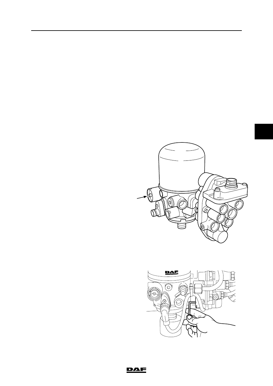
Connect a pressure gauge to the central 

drain/filler connection.

2.

Pressurise the air system.

3.

Check that the pressure regulator cuts out at 

the correct reading.

4.

If this is not the case, adjust the value using 

the screw on the air dryer (see arrow) as 

follows:

Adjusting the cut-out pressure
1.

If the cut-out pressure is too low, tighten the 

adjusting screw a little so that the cut-out 

pressure becomes too high.

2.

Ensure that the pressure regulator is 

switched on. If it is switched off, let some air 

escape through a reservoir until the system 

pressure falls beneath the cut-in pressure.

3.

Pressurise the air system to a little over 10 

bar.

4.

Unscrew the adjusting screw until the 

pressure regulator cuts out (see "Technical 

data").

5.

Check the cut-out pressure in the way 

mentioned above (see "Technical data").

Adjusting trailer vehicle system pressure
1.

Fit a pressure gauge to the trailer supply 

connection (red connection).

2.

Build up pressure in the brake system (air 

dryer should blow off).

3.

Check the pressure (see "Technical data").

4.

If necessary, adjust the pressure by turning 

the adjusting screw.

R600480

R600652

BRAKE SYSTEM AND COMPONENTS

2-16

©

 200436

Inspection and adjustment

4

ΛΦ45/55 series

6

2.11 CHECK AIR DRYER REGENERATION FUNCTION IN THE AIR SUPPLY UNIT

Air dryer regeneration function
1.

Pressurise the air system (pressure 

regulator should cut out).

2.

Switch the engine off.

3.

The regeneration air should escape via the 

vent opening of the air dryer, for 

approximately 20 seconds.

©

 200436

2-17

Inspection and adjustment

BRAKE SYSTEM AND COMPONENTS

ΛΦ45/55 series

6

4

2.12 CHECK THE 4-CIRCUIT SECURITY VALVE OF THE AIR SUPPLY UNIT

Check pressure build-up on circuits 1, 2, 3 
and 4
1.

Lower the pressure in the system to 0 bar.

2.

Connect pressure gauges to circuits 1, 2, 3 

and 4.

3.

Pressurise the circuits using the compressor 

(engine speed approx. 1000 rpm).

4.

The pressure in circuits 1, 2 and 4 will 

gradually increase. Once the opening 

pressure of circuit 3 has been reached (see 

"Technical Data"), the pressure in circuit 3 

will increase.

5.

If no more pressure builds up (cut-out 

pressure reached), the supply pressure in 

circuits 1, 2, 3 and 4 must meet the stipulated 

value (see "Technical Data".

Checking circuit 1
1.

Turn off the engine and simulate a leak in 

circuit 1.

2.

The pressure in circuit 2 and 4 may not fall 

below the specified closing pressure of 

circuit 1. See "Technical data".

Checking circuit 2
1.

Make sure the leak in circuit 1 is remedied 

and pressurise the system again.

2.

Turn off the engine and simulate a leak in 

circuit 2.

3.

The pressure in circuit 1 and 4 may not fall 

below the specified closing pressure of 

circuit 2. See "Technical data".

Checking circuit 3
1.

Make sure the leak in circuit 2 is remedied 

and pressurise the system again.

2.

Turn off the engine and simulate a leak in 

circuit 3 for the trailer circuit (connection 

point 23).

3.

The pressure in circuit 1.2 and 4 may not fall 

below the specified closing pressure of 

circuit 3. See "Technical data".

4.

The pressure in circuit 3 for the parking brake 

circuit (connection point 25) must remain 

secured by the check valve.

Checking circuit 4
1.

Make sure the leak in circuit 3 is remedied 

and pressurise the system again.

2.

Turn off the engine and simulate a leak in 

circuit 4.

3.

The pressure in circuit 1 and 2 may not fall 

below the specified closing pressure of 

circuit 4. See "Technical data".

BRAKE SYSTEM AND COMPONENTS

2-18

©

 200436

Inspection and adjustment

4

ΛΦ45/55 series

6

Checking circuit 3 flow-back function
1.

Make sure the leak in circuit 4 is remedied 

and pressurise the system again.

2.

Turn off the engine and simulate a leak in 

circuit 1.

3.

The pressure in circuit 3 for the trailer circuit 

(connection point 23) will decrease to 0 bar 

when the pressure in circuit 1 has reached 

the activation pressure for the flow-back 

function. See "Technical data".


Content   ..  457  458  459  460   ..