DAF LF45, LF55 Series. Manual - part 453
©
200436
2-33
Description of components
OPERATION OF BRAKE COMPONENTS
ΛΦ45/55 series
6
3
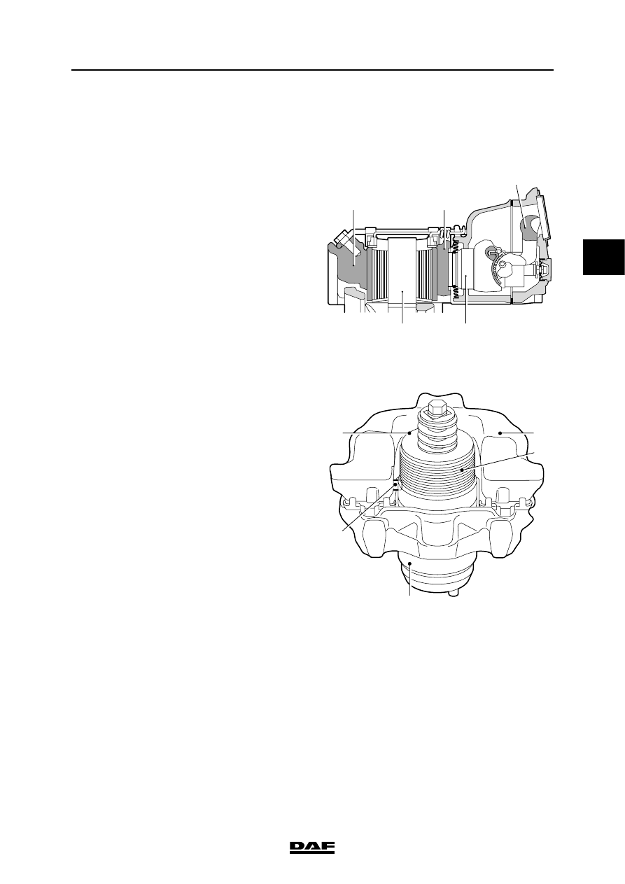
2.18 DISC BRAKE CONSTRUCTION, WABCO MODEL
PAN 17 and PAN 19-1+ versions
Operation
Brakes
This disc brake operates using a pneumatic
brake cylinder or spring brake cylinder.
If the brake is applied, the brake cylinder push
rod presses against the eccentrically mounted
lever (1).
Via brake cylinder 2 and pressure plate 3, the
brake pad is pressed against the inside of the
brake disc (4).
Due to the reaction force at the eccentric, the
floating brake calliper (5) will also press the
opposite brake pad with the same force.
Adjusting
If the eccentrically mounted lever (6) is operated
by the push rod of the brake cylinder, the pin (7)
on the lever will rotate the adjuster (8) and the
pressure cylinder (9) in the outgoing stroke until
the play has been eliminated.
If the brake is no longer being operated, the
lever (6) will turn the adjuster (8) back in the
opposite direction. The spring (10) in the adjuster
will ensure that the pressure cylinder will hardly
rotate. The result is that a small total play of about
0.5 mm will remain between the brake pads and
brake disc.
Brake pad wear wires
Brake pad wear wires are fitted to the brake pads.
These wires are cut through when the brake
lining has been worn down to the minimum
thickness.
This is the signal for the VIC system to activate
the "brake pad wear" warning symbol on DIP-4.
R600573
R600574
1
3
5
4
2
R600579
9
7
8
6
10