DAF LF45, LF55 Series. Manual - part 315
 

  Index      DAF     DAF LF45, LF55 Series - service repair manual


Search            


Content   ..  313  314  315  316   ..


DAF LF45, LF55 Series. Manual - part 315


©

 200416

4-3

Inspection and adjustment

CE ENGINE FUEL SYSTEM

ΛΦ45/55 series

4

5

6.

Bleed the fuel system, start the engine and 

check the fuel system visually for leaks if no 

further measurements are to be carried out.

Checking fuel pressure in fuel lift pump after 
fuel fine filter
1.

Disconnect the fuel pipe from the fuel fine 

filter to the high-pressure pump on the side of 

the high-pressure pump; see "Removal and 

installation".

2.

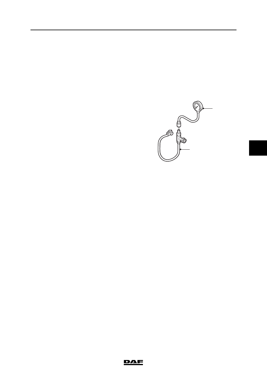
Fit the adapter (1), special tool 

(DAF no. 1329476), between the pipe which 

has been removed and the high-pressure 

pump and couple a pressure gauge (2) to 

this adapter.

3.

Bleed the fuel system.

4.

Disconnect the electrical connectors of the 

injectors from the valve sleeve.

5.

Start the engine and measure the pressure 

when the engine is idling. Compare the 

readings with the specified values. See 

"Technical data".

6.

Connect the electrical connectors of the 

injectors to the valve sleeve.

7.

Remove the pressure gauge and the adapter 

and reconnect the fuel pipe.

8.

Bleed the fuel system, start the engine and 

check the fuel system visually for leaks if no 

further measurements are to be carried out.

Check pressure drop across fuel fine filter
1.

Check the fuel pressure in front of the fuel 

fine filter.

2.

Check the fuel pressure after the fuel fine 

filter at maximum engine speed.

3.

Compare the measured pressure drop 

across the fuel fine filter with the specified 

value. See "Technical data". If the pressure 

drop is too great, the fuel fine filter must be 

replaced.

i400883

2

1

CE ENGINE FUEL SYSTEM

4-4

©

 200416

Inspection and adjustment

5

ΛΦ45/55 series

4

4.3 INSPECTION, INTERNAL FUEL LEAKS

When inspecting for internal fuel 

leaks, fuel will escape. Collect the 

fuel and avoid the risk of fire. 

Dirt in the fuel system can lead to 

significant damage to parts of the 

system. All open connections must 

therefore be sealed.

The common rail system is under 

high pressure when the engine is 

running. This pressure can rise to 

approx. 1400 bar. Even when the 

engine is not running, there may be 

a high residual pressure in the fuel 

rail (approx. 50 bar). Depressurise 

the system before working on the 

common rail system by wrapping the 

coupling in a cloth and then 

unscrewing it and collecting the 

escaping fuel in a container.

Inspection, internal fuel leaks
1.

Check that all injector pipes have been 

tightened to the correct torque and that there 

are no external signs of fuel leakage; see 

"Technical data".

2.

Disconnect the fuel return pipe (1) from the 

fuel return overflow valve (2) on the rear of 

the cylinder head. 

}

}

}

i400679

1

2

©

 200416

4-5

Inspection and adjustment

CE ENGINE FUEL SYSTEM

ΛΦ45/55 series

4

5

3.

Seal the disconnected fuel pipe (1) using the 

special tool (DAF no. 1453151) to prevent 

the return fuel escaping.

4.

Fit the special tool (DAF no. 1329476) onto 

the fuel return overflow valve (2).

5.

Place the free end of the special tool 

(DAF no. 1329476) in a container and start 

the engine.

6.

While the engine is idling, measure the 

quantity of return fuel using a stop watch and 

a measuring beaker; see "Technical data" for 

the maximum quantity of return fuel.

Note:

If the quantity of return fuel is within the 

specified value there are no internal leaks.

If the quantity of return fuel exceeds the 

specified value, the internal fuel leak must be 

located.

1

2

i400680

i400682

CE ENGINE FUEL SYSTEM

4-6

©

 200416

Inspection and adjustment

5

ΛΦ45/55 series

4

Locating internal fuel leak
1.

Take the injector pipe out of cylinder 1.

2.

Seal the connection of cylinder 1 on the fuel 

rail using the special tool 

(DAF no. 1453133). Tighten the plug to 30 

Nm.

3.

While the engine is idling, use a stop watch 

to measure the time required to fill a 

measuring beaker with 360 ml of return fuel. 

See "Technical data" for the minimum time 

permitted for filling the measuring beaker.

Note:

Use a measuring beaker with a mark at 

360ml.

4.

Remove the special tool (DAF no. 1453133) 

and reconnect the injector pipe.

5.

Repeat the above steps for the other 

cylinders and note the values.

Note:

When the leaking cylinder has been plugged, 

the quantity of return fuel will decrease and, 

as a result, the time it takes to fill the 

measuring beaker to 360ml will increase.

If several high values are measured, this 

indicates that there may be several leaks. If 

this is the case, first check the cylinders that 

give the highest values and then repeat the 

test.

In the example shown in the table below 

there is an internal leak in the 5

rd

 cylinder, 

which could be caused by a leak in the fuel 

supply pipe and/or a defective injector.

Example:

6.

In the event of a leak, remove the fuel supply 

pipe and the injector of the cylinder in 

question; see "Removal and installation".

i400681

Leak test results

Blocked cylinder

1

2

3

4

5

6

Time (s) to fill to 360ml

35

36

35

37

150

38


Content   ..  313  314  315  316   ..