DAF LF45, LF55 Series. Manual - part 225


  Index      DAF     DAF LF45, LF55 Series - service repair manual


Search            


Content   ..  223  224  225  226   ..


DAF LF45, LF55 Series. Manual - part 225


©

 200508

4-1

Automatic gearbox

DIAGNOSTICS

ΛΦ45/55 series

3

1

4. AUTOMATIC GEARBOX

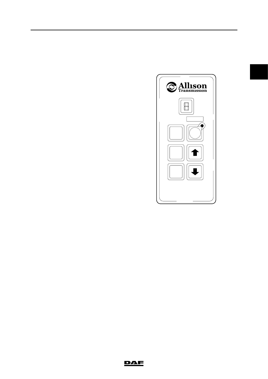
4.1 READING/DELETING ALLISON MD 3060 FAULT CODES

Fault code read function
To enter the fault code reading mode, briefly 

press the two arrow keys twice simultaneously.

"D-1" appears on the display, followed by "-".

This means that at that point there are no faults 

(active faults) in the system. It also means that no 

faults have been registered that were earlier 

temporarily present and have now been cleared 

(inactive faults). The fault code reading function 

can be left by pressing "D", "N", or "R" or the 

arrow keys.

If the red lamp lights up while reading a fault 

code, this means that there is an active fault in the 

gearbox.

No message during reading means that the fault 

is inactive.

The ECU can save five active/inactive fault codes 

in its memory and show them on the display. 

Fault codes consist of two sets of two digits (main 

codes and sub-codes). To read the codes 

consecutively, the "MODE" button must be 

pressed each time.

The letters and digits appear one at a time on the 

display.

The hyphen after D4 means that there are no 

further faults and that it is therefore not necessary 

to look at level D5.

As the ECU can only contain the five most 

important codes, the five most important codes 

will be seen on D1 to D5. Only when one of the 

faults has been remedied will the ECU be in a 

position to show a less important fault.

R

D

MODE

N

V300392

Example:

D1

25 - 22

D2

21 - 12

D3

24 - 12

D4

-

DIAGNOSTICS

4-2

©

 200508

Automatic gearbox

1

ΛΦ45/55 series

3

Deleting fault codes
After faults have been remedied, the ECU 

memory must be deleted. This is done as follows.

Press the arrow keys twice simultaneously. This 

is the fault code reading mode. Press the 

"MODE" key and hold it down until the red lamp 

flashes three times (the first flash will be after 

approx. three seconds, the second after approx. 

10 seconds). All codes, active or inactive, have 

now been deleted. Codes which return following 

deleting and can therefore no longer be deleted 

are active. Both types of fault need their causes 

tracing and remedying as quickly as possible.

After the fault codes have been deleted the 

ignition must be switched off and re-started; 

otherwise it will not be possible to drive. This can 

be seen from the flashing of the gear lever 

position.

Inactive faults are automatically deleted by the 

ECU if the fault no longer occurs after the vehicle 

ignition has been switched off and on 25 times.

It is not possible to remedy all fault codes. Fault 

codes that cannot be found in the "Table of Fault 

Codes" can best be remedied by an Allison 

dealer.

He has test and diagnostic apparatus at his 

disposal that can be connected to a special 

diagnostic socket in the central box (next to the 

DAVIE connector).

R

D

MODE

N

V300392

©

 200508

4-3

Automatic gearbox

DIAGNOSTICS

ΛΦ45/55 series

3

1

4.2 ALLISON MD 3060 TABLE OF FAULT CODES

Main code Sub-code

RECOMMENDED PROCEDURES

Electronic control unit (ECU) supply

13

12 Low

23 High

Check the following points:

1.

earth and positive battery cables connected, firmly attached and clean.

2.

batteries are charged.

3.

vehicle loading system fails to load or loads too little or too much.

4.

VIM fuse (Vehicle Interface Module).

5.

VIM connections are firmly attached, clean and undamaged.

6.

the correct wiring is used.

7.

ECU connections are firmly attached, clean and undamaged.

If all these points are in order, contact your Allison dealer.

Accelerator pedal sensor

21

12

23

Check the following points:

1.

Accelerator pedal sensor connector is properly connected.

2.

no interruptions or short circuits between wires or earth in wiring harness 

to accelerator pedal sensor.

Replace the accelerator pedal sensor if necessary.

If all these points are in order, contact your Allison dealer.

Main code Sub-code

RECOMMENDED PROCEDURES

Speed sensors

22

14

15

16

Check the following points:

1.

connectors are firmly attached, clean and undamaged.

2.

the speed sensor attachment bolt is tightened to the specified torque.

3.

no interruptions or short circuits between wires or earth in wiring harness 

to sensor.

If all these points are in order, contact your Allison dealer.

Selector keypad

23

12

13

14

15

23

24

Check the following points:

1.

ECU connections - connectors are connected and clamped.

2.

selector keypad is connected and the wire loop has been cut through.

3.

no interruptions or short circuits between wires or earth in wiring harness 

to selector.

Replace the selector if possible.

If all these points are in order, contact your Allison dealer.

Temperature in the gearbox sump too low

24

12

Check the following points:

1.

temperature is lower than -6

″C.

1.

If this is the case, it is a normal response to the ambient temperature.

2.

If not, check whether the main gearbox is firmly connected and that 

the connectors are undamaged.

If all these points are in order, contact your Allison dealer.

DIAGNOSTICS

4-4

©

 200508

Automatic gearbox

1

ΛΦ45/55 series

3

Main code Sub-code

RECOMMENDED PROCEDURES

Temperature in the gearbox sump is too high

24

23

1.

Run the engine at idling speed.

2.

Ensure that the vehicle is entirely horizontal.

3.

Check whether the correct dip stick has been installed.

4.

Check the oil level.

5.

If necessary, correct the oil level.

6.

If the oil level is in order, check whether the engine system has 

overheated, causing the gearbox to overheat.

7.

Check that the ECU and gearbox connectors are correctly connected, 

firmly attached and undamaged.

If all these points are in order, contact your Allison dealer.

Output shaft speed sensor

25

00

11

22

33

44

55

66

77

Check the following points:

1.

connector is connected.

2.

sensor bolt is firmly attached.

3.

ECU is firmly attached with no damaged connectors.

4.

oil level.

5.

no interruptions or short circuits between wires or earth in wiring harness 

to sensor.

If all these points are in order, contact your Allison dealer.

Coupling 3 pressure switch open

32

00

33

55

77

1.

Let the engine idle while the vehicle's parking brake is applied.

Check the following points:

1.

specified dip stick.

2.

correct oil level.

2.

Check the following points:

1.

gearbox main connector is connected, is firmly attached, is clean 

and undamaged.

2.

ECU connector is connected, is firmly attached, is clean and 

undamaged.

3.

no interruptions or short circuits between wires or earth in wiring 

harness.

If all these points are in order, contact your Allison dealer.

Main code Sub-code

RECOMMENDED PROCEDURES

Sensor fault in gearbox oil sump

33

12

23

Check the following points:

1.

gearbox main connector is connected, is firmly attached, is clean and 

undamaged.

2.

ECU connector is connected, is firmly attached, is clean and undamaged.

3.

no interruptions or short circuits between wires or earth in wiring harness.

If all these points are in order, contact your Allison dealer.


Content   ..  223  224  225  226   ..