DAF 95XF. Manual - part 785
9
REAR AXLE ALIGNMENT
Inspection and adjustment
2-6
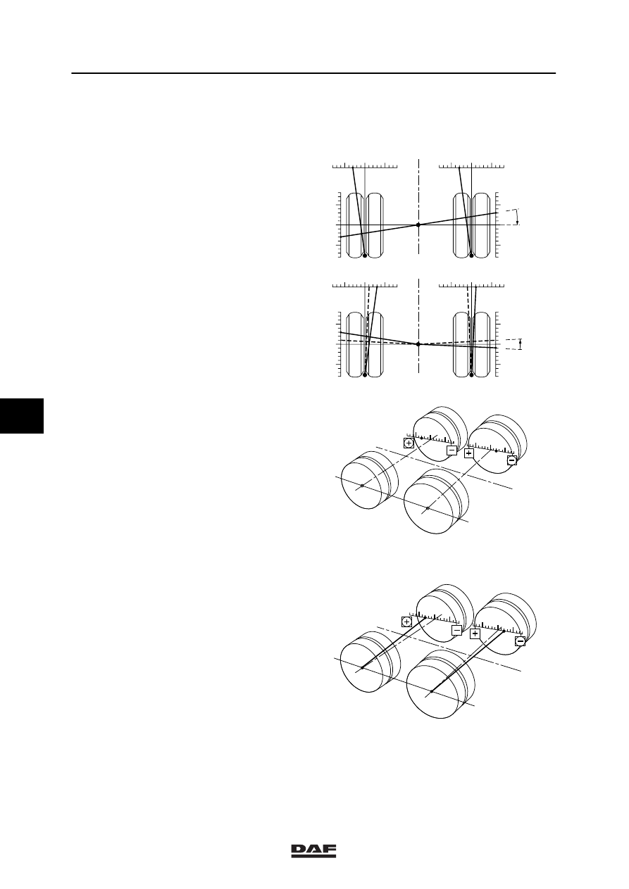
Example 3
This example refers to a vehicle with two rear
axles.
1.
The adjacent illustration shows the axles
from the previous examples. The positions
of the two axles in relation to the vehicle
centreline have already been determined.
2.
The angle (in mm/m) through which the
axles should have to be rotated in order for
them to be realigned in relation to the
vehicle centreline, corresponds with the
misalignment in relation to the vehicle
centreline.
Enter these values in the scale of the figure
at the bottom of drawing 11. Take care to
enter this value on the correct side (+ or
-- side) of the vehicle centreline indicated in
this drawing.
3.
From the small circle in the left wheels,
draw a straight line to the values on the
scale (illustration 12).
The position of the two axles in relation to
each other is now visible. It can now be
determined whether realigning is required
and which axle must be realigned.
If necessary, the required realignment can
also be indicated as a dotted line in the
figure.
Note:
Often it is only necessary to realign one of
the axles to ensure that the non-parallelism
of both axles in relation to each other is
within the permitted tolerance limits.
4.
The non-parallelism in this example is
5 mm/m. In this case it is therefore
sufficient to realign the front axle only.
Note:
The realignment option depends on the
type of axle suspension.
-
+
+
-
-
+
+
-
1
1
3
3
2mm/m
1
1
1
1
-
+
+
-
-
+
+
-
3
3
3
3
3mm/m
3
2
Afb. 11
W9 08 012
3
2
W9 08 013
Afb. 12
6
ǹ 200316