Citroen C5 (2017 year). Instruction - part 14
 

  Index      Citroen     Citroen C5 - instruction 2017 year in english


Search            


Content   ..  12  13  14  15   ..


Citroen C5 (2017 year). Instruction - part 14


8

In the event of a breakdown

207

C5_en_Chap08_en-cas-de-panne_ed01-2016

F

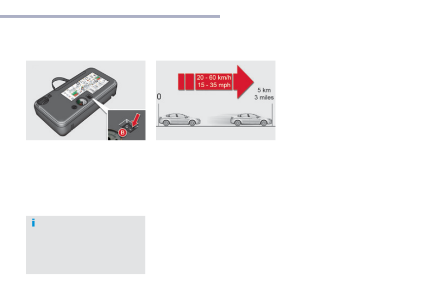
  Switch on the compressor by moving 

the switch B to position "I" until the tyre 
pressure reaches 2.0 bars.


The sealant is injected into the tyre under 
pressure; do not disconnect the pipe from 
the valve during this operation (risk of 
splashing).

F

  Remove the kit and screw the cap back on 

the white pipe.


Take care to avoid staining your vehicle 
with traces of fluid. Keep the kit to hand.

F

  Drive immediately for approximately 

three miles (five kilometres), at reduced 
speed (between 12 and 37 mph (20 and 
60 km/h)), to plug the puncture.

F

  Stop to check the repair and the tyre 

pressure using the kit.

If after around 5 to 7 minutes the 
pressure is not attained, this indicates 
that the tyre is not repairable; contact 
a CITROËN dealer or a qualified 
workshop for assistance.

In the event of a breakdown

208

C5_en_Chap08_en-cas-de-panne_ed01-2016

2. Inflation

F  Turn the selector A to the "Air" 

position.

F  Uncoil the white pipe G

 fully.

F

  Connect the white pipe to the tyre valve.

F

  Connect the compressor's electric plug to 

the vehicle's 12 V socket.

F

  Start the vehicle again and leave the 

engine running.

As soon as possible, go to a CITROËN 
dealer or a qualified workshop.
You must inform the technician that you 
have used this kit. After inspection, the 
technician will advise you on whether 
the tyre can be repaired or if it must be 
replaced.

F

  Adjust the pressure using the compressor 

(to inflate: switch B in position "I"; to 
deflate: switch B in position "O" and press 
button C

), in accordance with the vehicle's 

tyre pressure label (located on the left-
hand door aperture).


A loss of pressure indicates that the 
puncture has not been fully plugged; 
contact a CITROËN dealer or qualified 
workshop for assistance.

F

  Remove and stow the kit.

F

  Drive at reduced speed (50 mph [80 km/h] 

max) limiting the distance travelled to 
approximately 120 miles (200 km).

8

In the event of a breakdown

209

C5_en_Chap08_en-cas-de-panne_ed01-2016

Removing the pipe and cartridge

F

  Turn the pipe assembly 2 to the left until it 

contacts the unit.

F  Disconnect the union 1

 from the cartridge 

by turning it a quarter turn anti-clockwise.

F

  Extract the pipe assembly 2, then 

disconnect the union 3

 from the air delivery 

pipe by turning it a quarter turn anti-
clockwise.

Beware of discharges of fluid.
The expiry date of the fluid is indicated 
on the cartridge.
The sealant cartridge is designed for 
single use; even if only partly used, it 
must be replaced.
After use, do not discard the cartridge 
into the environment, take it to an 
authorised waste disposal site or a 
CITROËN dealer.
Do not forget to obtain a new sealant 
cartridge, available from CITROËN 
dealers or from a qualified workshop.

F

  Remove the pipe assembly 2.

F

  Support the compressor vertically.

F

  Unscrew the cartridge 4 from the bottom.

To fit the new cartridge and new pipe, carry out 
these operations in reverse order.

In the event of a breakdown

210

C5_en_Chap08_en-cas-de-panne_ed01-2016

Checking / adjusting tyre pressures

You can also use the compressor without 
injecting any product, to check and if necessary 
adjust your tyre pressures.

F  Turn the selector A to the "Air" 

position.

F  Uncoil the white pipe G

 fully.

F

  Connect the pipe to the tyre valve.

F

  Connect the compressor's electrical 

connector to the vehicle's 12 V socket.

F

  Start the vehicle and let the engine run.

F

  Adjust the pressure using the compressor 

(to inflate: switch B in position "I"
to deflate: switch B in position "O" and 
press button C

), according to the vehicle's 

tyre pressure label.

F

  Remove the kit then stow it.

8

In the event of a breakdown

211

C5_en_Chap08_en-cas-de-panne_ed01-2016

Changing a wheel

Access to the tools

For vehicles supplied with a standard spare 
wheel

 (same size as the four wheels), the tools 

are stowed in a carrier, located in the spare 
wheel.
F

  Release the retaining strap for access to it.

List of tools

All of these tools are specific to your vehicle 
and may vary according to equipment. Do not 
use them for any other purpose.

1.

  Wheelbrace.


Used for removing the wheel trim and the 
wheel fixing bolts.

2.

  Jack with integral handle.


Used to raise the vehicle.

3.

  Bolt head finisher tool.


Used to remove the wheel bolt protectors 
(finishers) on wheel bolts with alloy wheels.

4.

  Wheel chock*.

5.

  Towing eye.

Do not use:
-  the jack for any purpose other than 

lifting the vehicle,

-  a different jack from the one 

supplied with the vehicle.

If the vehicle does not have its original 
jack, contact a CITROËN dealer or a 
qualified workshop to obtain the one 
listed by the manufacturer.

For more information on Towing the 
vehicle

, refer to the corresponding 

section.

* Depending on country of sale.

For vehicles supplied with a "space-saver" 
type spare wheel
, the tools are stowed in a 
storage well, located below the spare wheel.
F  Unscrew the central yellow screw and 

remove the wheel for access to it.

In the event of a breakdown

212

C5_en_Chap08_en-cas-de-panne_ed01-2016

Access to the spare wheel

Removing the boot floor

F  Saloon

: raise the boot floor and fold in two.

F  Tourer

: raise the boot floor and hook it 

using the retractable handle. Secure the 
hook to the top part of the boot.

Removing the standard spare 
wheel

F  Detach the strap, then push the wheel 

forwards so as to be able to lift it.

Repositioning the standard spare 
wheel

F  Position the spare wheel flat in the boot, 

then pull it towards you.

F

  Next place the toolbox inside the wheel, 

then secure the assembly using the strap.

Removing the "space-saver" 
spare wheel

F

  Unscrew the central nut.

F

  Remove the fixing parts (nut and bolt).

F

  Take the spare wheel from the rear and lift 

it towards you.

F

  Remove the wheel from the boot.

8

In the event of a breakdown

213

C5_en_Chap08_en-cas-de-panne_ed01-2016

The tyre pressures are indicated on the 
label located on the left-hand centre 
door pillar.
Tyre pressures are given on this label 
for different vehicle loading conditions.

Repositioning the "space-saver" 
spare wheel

F

  Return the spare wheel to its housing 

above the toolbox.

F

  Unscrew the nut on the bolt by a few turns.

F

  Place the fixing parts (nut and bolt) in the 

middle of the wheel.

F

  Tighten the central nut until it clicks to 

secure the wheel.

Repositioning the boot floor

F  Release the boot floor to return it to its 

initial position.

In the event of a breakdown

214

C5_en_Chap08_en-cas-de-panne_ed01-2016

Removing a wheel

F

  Park the vehicle on stable, firm ground that 

is not slippery. Apply the parking brake.

F

  If your vehicle is equipped with 

"Hydractive III+" suspension, with the 
engine running at idle, adjust the ground 
clearance to its maximum height.

F

  Switch off the ignition and engage first gear 

(position P for an automatic gearbox).

F  If your vehicle is fitted with "Hydractive III+" 

suspension, position the chock, whichever 
direction the gradient may be in, in front of 
the front wheel diametrically opposite to 
the one to be replaced.

List of operations

F

  Remove the protector from each bolt using 

tool 3

.

F

  Fit the security bolt socket to the 

wheelbrace to slacken the security bolt 
(depending on equipment).

F

  Slacken the other bolts using just the 

wheelbrace 1

.

Before positioning the jack:
F

  Always adjust the vehicle’s ground 

clearance to the "maximum height" 
position and retain this adjustment 
for as long as the jack is under the 
vehicle (do not use the hydraulic 
adjustments),

F

  Ensure that any passengers have 

left the vehicle and are in a safe 
place.

Never go underneath the vehicle if it is 
supported only by the jack.
The jack and all of the tools are specific 
to your vehicle. Do not use them for any 
other purposes.
Have the original wheel repaired and 
refitted as soon as possible.

8

In the event of a breakdown

215

C5_en_Chap08_en-cas-de-panne_ed01-2016

F

  Position the foot of the jack 2 on the 

ground, ensuring that it is directly below the 
front A or rear B

 jacking point provided on 

the underbody, closest to the wheel to be 
changed.

Ensure that the jack is stable. If the 
ground is slippery or loose, the jack 
may slip or drop - Risk of injury!
Ensure that the jack is positioned only 
at one of the jacking points provided 
under the vehicle, making sure that the 
vehicle's contact area is centred on the 
head of the jack. Otherwise there is a 
risk of damage to the vehicle and/or of 
the jack dropping - Risk of injury!

F

  Extend the jack 2 until its head comes into 

contact with the jacking point A or B used; 
the contact area A or B

 on the vehicle must 

be correctly inserted into the central part of 
the head of the jack.

F  Raise the vehicle until there is sufficient 

space between the wheel and the ground 
to easily fit the spare (non punctured) 
wheel.

F

  Remove the bolts and stow them in a clean 

place.

F

  Remove the wheel.

In the event of a breakdown

216

C5_en_Chap08_en-cas-de-panne_ed01-2016

List of operations

Fitting a wheel

Wheel for temporary use

Your vehicle may be fitted with a spare wheel 
which is different to those on the vehicle. When 
fitting the spare wheel, it is normal to notice 
that the wheel bolt washers do not come into 
contact with the wheel rim. The spare wheel is 
secured by the conical tapering of the wheel 
bolt’s shaft.
When refitting the original wheel, ensure that 
the wheel bolt contact surfaces are clean and 
in good condition.

F

  Lower the vehicle to the ground.

F

  Lower the jack 2 and remove it.

F

  Fit the wheel on the hub.

F

  Fit and tighten the bolts by hand.

F

  Pre-tighten the security bolt using the 

wheelbrace 1 fitted with the security bolt 
socket (depending on equipment).

F

  Pre-tighten the other bolts using just the 

wheelbrace 1

.

8

In the event of a breakdown

217

C5_en_Chap08_en-cas-de-panne_ed01-2016

If your vehicle is fitted with a spare 
wheel of a different size to those on the 
vehicle, you must not exceed 50 mph 
(80 km/h) whilst using the spare wheel.
The wheel bolts are specific to the type 
of wheel.
If the type of wheel is changed, 
check with your CITROËN dealer or a 
qualified workshop that the wheel bolts 
are compatible with the new wheels.
Take care to note down the code 
number engraved on the head of the 
security bolt socket. This will enable 
you to obtain a replacement security 
bolt socket from your dealer.

F

  Tighten the security bolt using 

wheelbrace 1 fitted with the security bolt 
socket (depending on equipment).

F

  Tighten the other bolts using just the 

wheelbrace 1

.

F

  Refit the protectors on the bolts (depending 

on equipment).

F

  Stow the tools in the carrier box.

F

  Return the suspension to the normal 

position.

F

  Check that the tyre pressure is correct and 

have the balancing checked.

Tyre under-inflation detection

The space-saver type or steel spare 
wheel does not have a sensor.
The punctured wheel must be repaired 
by a CITROËN dealer or a qualified 
workshop.

In the event of a breakdown

218

C5_en_Chap08_en-cas-de-panne_ed01-2016

Changing a bulb

Front lamps

Model with Xenon headlamps (D1S)

1.  Dual-function Xenon headlamps 

(dipped/main): D1S

2.  Cornering lighting:

 HP19

3.  Daytime running lamps / sidelamps: 

LEDs

For the maintenance of the front lamps and 
changing HP19 and D1S bulbs and LED lamps, 
contact a CITROËN dealer or a qualified 
workshop.

Risk of electrocution
Xenon bulbs must be replaced by 
a CITROËN dealer or a qualified 
workshop.
You are advised to change both D1S 
bulbs at the same time, if one of them 
has failed.

The headlamps have polycarbonate 
lenses with a protective coating:
F  do not clean them using a dry 

or abrasive cloth, nor with a 
detergent or solvent product,

F

  use a sponge and soapy water or 

a pH neutral product,

F

  when using a high pressure washer 

on persistent marks, do not keep 
the lance directed towards the 
lamps or their edges for too long, 
so as not to damage their protective 
coating and seals.

Changing a bulb should only be done 
after the headlamp has been switched 
off for several minutes (risk of serious 
burns).
F  Do not touch the bulb directly with 

your fingers, use a lint-free cloth.

It is imperative to use only anti-
ultraviolet (UV) type bulbs to avoid 
damaging the headlamp.
Always replace a failed bulb with a 
new bulb with the same type and 
specification.

8

In the event of a breakdown

219

C5_en_Chap08_en-cas-de-panne_ed01-2016

Dipped beam headlamps

F

  Remove the protective cap B.

F

  Disconnect the connector by pressing it 

between the thumb and index finger.

F

  Free the bulb from its two metal clamps.

F

  Take out the bulb.

F

  Replace the bulb, exerting a slight axial 

force.

F

  Refit the connector, until it is all the way in.

F  Refit the protective cap B

.

Main beam headlamps

F

  Remove the protective cap A.

F

  Disengage the retaining spring.

F

  Remove the bulb and replace it, paying 

attention to the direction of fitting.

F

  Refit the retaining spring.

F  Refit the protective cap A

.

Model with halogen headlamps

1.  Main beams: H1
2.  Dipped beams:

 H7

3.  Directional lighting:

 H7

4.  Daytime running lamps / sidelamps: 

LEDs

For the maintenance of the front lamps and 
changing LED lamps, contact a CITROËN 
dealer or a qualified workshop.

In the event of a breakdown

220

C5_en_Chap08_en-cas-de-panne_ed01-2016

Directional lamp

F

  Remove the protective cap C.

F

  Disconnect the connector by pressing it 

between the thumb and index finger.

F

  Free the bulb from its two metal clamps.

F

  Take out the bulb.

F

  Replace the bulb, exerting a slight axial 

force.

F

  Refit the connector, until it is all the way in.

F  Refit the protective cap C

.

Direction indicators

F

  Refit the connector (push the grey tongue 

in well).

F

  Refit the headlamp unit in the bumper.

F

  Refit the lamp screws.

F

  Position the cover using its guides and refit 

the screws.

Bulbs:

 HP24

F

  Remove the fixing screw of cover A using a 

torx tool, tip the cover over and remove.

F

  Remove the fixing screw of lamp B using 

a torx tool, then pull the lamp to remove it 
from the bumper.

F  Detach the bulb C

 by pressing on bars 1 

and 2

.

F

  Disconnect the connector (pull whilst 

pressing on the grey tongue using a flat 
screwdriver).

F

  Replace the bulb.

8

In the event of a breakdown

221

C5_en_Chap08_en-cas-de-panne_ed01-2016

Side repeaters

The side repeater is sealed.
If the bulb is faulty, replace the side repeater.
Contact a CITROËN dealer or a qualified 
workshop.

Front foglamps

F  Disconnect the connector D

.

F

  Remove the bulb by performing a quarter 

of a turn.

F

  Replace the bulb.

F  Refit the connector D

.

F

  Refit the headlamp unit in the bumper.

F

  Refit the lamp screws.

F

  Position the cover using its guides and refit 

the screws.

When refitting, take care not to trap 
the electrical
 wiring.

Bulbs: H8
F

  Remove the fixing screw of cover A using a 

torx tool, tip the cover over and remove.

F

  Remove the fixing screw of lamp B using a 

torx tool, then pull on the lamp to remove it 
from the bumper.

In the event of a breakdown

222

C5_en_Chap08_en-cas-de-panne_ed01-2016

Rear lamps (Saloon)

Identify the failed bulb.
1.  Brake lamps and sidelamps:

 P21W/5W

2.  Sidelamps: R5W
3.  Reversing lamps: H21W
4.  Foglamps: H21W
5.  Direction indicators: PY21W

Boot lid-mounted lamps

F  Refit the bulb holder H

.

F

  Check that the bulb holder H is secured 

correctly by the two clips E

.

F  Refit the connector G

.

F

  Replace and fix the trim F with its 3 clips.

F

  Open the boot.

F

  Using a flat screwdriver, remove the 3 clips 

which fix the trim in the lamp area.

F

  Partially remove the trim F.

F  Disconnect the connector G

.

F  Unclip the bulb holder H

.

F

  Replace the failed bulb.


Content   ..  12  13  14  15   ..