Citroen Jumpy (2016 year). Instruction - part 19
 

  Index      Citroen     Citroen Jumpy - instruction 2016 year in english


Search            


Content   ..  17  18  19  20   ..


Citroen Jumpy (2016 year). Instruction - part 19


287

8

In the event of a breakdown

Jumpy_en_Chap08_En-cas-de-panne_ed01-2016

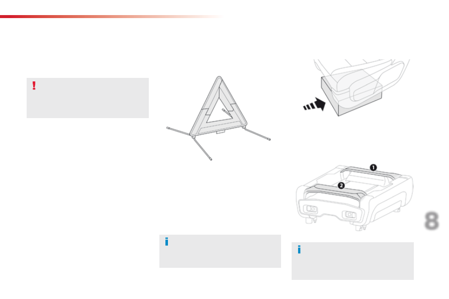
Warning triangle (stowing)

Before leaving your vehicle to set up 
and install the triangle, switch on the 
hazard warning lamps and put on your 
high visibility vest.

This safety equipment should be used in 
addition to the hazard warning lamps.
Its presence in the vehicle is mandatory.

Placing the triangle in the 
road

Refer to the manufacturer's instructions on 
unfolding and assembly supplied with the 
triangle.

F

  Place the triangle behind the vehicle, as 

required by the legislation in force in your 
country.

The triangle is available as an 
accessory; contact a CITROËN dealer 
or a qualified workshop.

Tool box

Access

The tool box is located under the left-hand front 
seat.

As a safety measure, the bars 1 and 2 
prevent the box escaping from its 
housing, if it is not correctly secured.

288

In the event of a breakdown

Jumpy_en_Chap08_En-cas-de-panne_ed01-2016

Stowing

F  Press the latches A and slide them inwards 

to release the box.

F

  Lift the box slightly then pull it as far as it 

will go to take it past bar 1.

F

  Then, lift the box upwards to take it past 

bar 2

.

F

  Unclip the fixings B on the cover, then 

open it for access to the tools.

Opening

Removing

Pull on the box to check that it is secure 
in its housing.

F  Offer up the box with the front inclined 

upwards.

F

  To take it past bar 2, push the box in and 

down.

F

  To take it past bar 1, raise the box slightly 

then push it fully in.

F  Refit the cover on the box and clip the 

fixings B.

F  Once the box is fully home

 in its housing, 

push it against the floor carpet then slide 
the latches A

 outwards to secure it.

289

8

In the event of a breakdown

Jumpy_en_Chap08_En-cas-de-panne_ed01-2016

If your vehicle is equipped 
with a temporary puncture 
repair kit

1.

  12 V compressor.


To temporarily repair a tyre using an 
integral sealant cartridge and adjust the 
tyre pressure.

2.

  Towing eye.

If your vehicle is equipped 
with a spare wheel

1.

  Wheelbrace.


For removing the wheel bolts and raising/
lowering the jack.

2.

  Jack.


For raising the vehicle.

3.

  Wheel bolt cap/wheel trim removal tools.


If your vehicle is so equipped, for removing 
the wheel bolt head covers on alloy wheels 
or the wheel trim on steel wheels.

4.

  Security bolt socket.


For adapting the wheelbrace to the special 
"security" bolts.

5.

  Towing eye.

These tools are specific to your vehicle 
and can vary according to equipment. 
Do not use them for other purposes.

290

In the event of a breakdown

Jumpy_en_Chap08_En-cas-de-panne_ed01-2016

This kit is stowed in the tool box.

This kit consists of a compressor and a sealant 
cartridge.
It allows the temporary repair

 of a tyre.

You are then able to go to the nearest garage.
It is designed to repair most punctures which 
could affect the tyre, located on the tyre tread 
or shoulder.
Its compressor can be used to check and 
adjust the pressure of the tyre.

Temporary puncture repair kit

Access to the kit

1.

  12 V compressor.


To temporarily repair a tyre using an 
integral sealant cartridge and adjust the 
tyre pressure.

2.

  Towing eye.

The tyre inflation pressures are given on this 
label.

The vehicle's electric system allows the 
connection of the compressor for long 
enough to inflate a tyre after a puncture 
repair.
Use only the two 12 V sockets 
located at the front to connect your 
compressor.

For more information on Towing, refer 
to the corresponding section.

List of tools

These tools are specific to your vehicle and can 
vary according to equipment. Do not use them 
for other purposes.

For more information on the Tool box
refer to the corresponding section.

291

8

In the event of a breakdown

Jumpy_en_Chap08_En-cas-de-panne_ed01-2016

A.

  "Sealant" or "Air" position selector.

B. On 

"I"

 / off "O" switch.

C.

  Deflation button.

D.

  Pressure gauge (in bars and psi).

E.

  Compartment housing a cable with an 

adaptor for a 12 V socket.

Description of the kit

F.

  Sealant cartridge.

G.

  White pipe with cap for repair.

H.

  Black pipe for inflation.

I.

  Speed limit sticker.

The speed limit sticker I must be affixed 
to the vehicle's steering wheel to remind 
you that a wheel is in temporary use.
Do not exceed a speed of 50 mph 
(80 km/h) when driving with a tyre 
repaired using this type of kit.

292

In the event of a breakdown

Jumpy_en_Chap08_En-cas-de-panne_ed01-2016

Repair procedure

1. Sealing

F  Uncoil the white pipe G

 fully.

F

  Unscrew the cap from the white pipe.

F  Connect the white pipe to the valve of the 

tyre to be repaired.

F

  Connect the compressor's electric plug to 

the vehicle's 12 V socket.

F

  Start the vehicle and leave the engine 

running.

Take care, this product is harmful if 
swallowed and causes irritation to the 
eyes.
Keep this product out of the reach of 
children.

Avoid removing any foreign bodies 
which have penetrated into the tyre.

Do not start the compressor before 
connecting the white pipe to the tyre 
valve: the sealant product would be 
expelled through the pipe.

F

  Switch off the ignition.

F  Turn the selector A to the 

"sealant" position.

F

  Check that the switch B is in position "O".

293

8

In the event of a breakdown

Jumpy_en_Chap08_En-cas-de-panne_ed01-2016

If after around 5 to 7 minutes the 
pressure is not attained, this indicates 
that the tyre is not repairable; contact 
a CITROËN dealer or a qualified 
workshop for assistance.

F

  Switch on the compressor by moving 

the switch B to position "I" until the tyre 
pressure reaches 2.0 bars.


The sealant is injected into the tyre under 
pressure; do not disconnect the pipe from 
the valve during this operation (risk of 
splashing).

F

  Remove the kit and screw the cap back on 

the white pipe.


Take care to avoid staining your vehicle 
with traces of fluid. Keep the kit to hand.

2. Inflation

F  Turn the selector A to the "Air" 

position.

F

  Uncoil the black pipe H fully.

F

  Connect the black pipe to the valve of the 

wheel.

F  Drive immediately for approximately 

three miles (five kilometres), at 
reduced speed (between 15 and 35 mph 
(20 and 60 km/h)), to plug the puncture.

F

  Stop to check the repair and the tyre 

pressure using the kit.

294

In the event of a breakdown

Jumpy_en_Chap08_En-cas-de-panne_ed01-2016

F

  Connect the compressor's electric plug to 

the vehicle's 12 V socket.

F

  Start the vehicle again and leave the 

engine running.

F

  Adjust the pressure using the compressor 

(to inflate: switch B in position "I"; to 
deflate: switch B in position "O" and press 
button C

), in accordance with the vehicle's 

tyre pressure label (located on the left 
hand door aperture). 


A loss of pressure indicates that the 
puncture has not been fully plugged; 
contact a CITROËN dealer or qualified 
workshop for assistance.

F

  Remove and stow the kit.

F

  Drive at reduced speed (50 mph [80 km/h] 

max) limiting the distance travelled to 
approximately 120 miles (200 km).

As soon as possible, go to a CITROËN 
dealer or a qualified workshop.
You must inform the technician that you 
have used this kit. After inspection, the 
technician will advise you on whether 
the tyre can be repaired or if it must be 
replaced.

Removing the cartridge

F

  Stow the black pipe.

F

  Detach the angled base from the white pipe.

F

  Support the compressor vertically.

Beware of discharges of fluid.
The expiry date of the fluid is indicated 
on the cartridge.
The sealant cartridge is designed for 
single use; even if only partly used, it 
must be replaced.
After use, do not discard the cartridge 
into the environment, take it to an 
authorised waste disposal site or a 
CITROËN dealer.
Do not forget to obtain a new sealant 
cartridge, available from CITROËN 
dealers or from a qualified workshop.

F

  Unscrew the cartridge from the bottom.

295

8

In the event of a breakdown

Jumpy_en_Chap08_En-cas-de-panne_ed01-2016

Checking / adjusting tyre 
pressures

You can also use the compressor without 
injecting any product, to check and if necessary 
adjust your tyre pressures.

F  Turn the selector A to the "Air" 

position.

F

  Connect the compressor's electrical 

connector to the vehicle's 12 V socket.

F

  Start the vehicle and let the engine run.

F

  Adjust the pressure using the compressor 

(to inflate: switch B in position "I"; to 
deflate: switch B in position "O" and press 
button C

), according to the vehicle's tyre 

pressure label.

F

  Remove the kit then stow it.

Should the pressure of one or more 
tyres be adjusted, it is necessary to 
reinitialise the under-inflation detection 
system.
For more information on Under-
inflation detection
, refer to the 
corresponding section.

F

  Uncoil the black pipe H fully.

F

  Connect the black pipe to the tyre valve.

296

In the event of a breakdown

Jumpy_en_Chap08_En-cas-de-panne_ed01-2016

Changing a wheel

The tools are stowed in the tool box.

Access to the tooling

1.

  Wheelbrace.


For removing the wheel bolts and raising/
lowering the jack.

2.

  Jack.


For raising the vehicle.

3.

  Wheel bolt cap/wheel trim removal tool.


If your vehicle is so equipped, for removing 
the wheel bolt head covers on alloy wheels 
or the central wheel trim on steel wheels.

4.

  Socket for the security bolts.


For adapting the wheelbrace to the special 
"security" bolts.

5.

  Towing eye.

For more information on Towing, refer 
to the corresponding section.

The jack must only be used to change a 
wheel with a damaged tyre.
The jack does not require any 
maintenance.

The jack conforms to European 
legislation, such as defined in the 
Machinery Directive 2006/42/CE.

List of tools

These tools are specific to your vehicle and can 
vary according to the level of equipment. Do 
not use them for other purposes.

For more information on the Tool box
refer to the corresponding section.

297

8

In the event of a breakdown

Jumpy_en_Chap08_En-cas-de-panne_ed01-2016

F

  Access to the spare wheel is from the rear.

F

  Open the side-hinged rear doors or the 

tailgate, according to the configuration of 
your vehicle.

F  Access the carrier bolt, located on the rear 

door sill.

F

  Turn the bolt anti-clockwise using the 

wheelbrace (about 14 turns) until the 
carrier is low enough to allow the carrier 
hook to be disengaged.

Access to the spare wheel

F  If your vehicle is fitted with a towbar, raise 

the rear of the vehicle using the jack (must 
be at jacking point B) to allow sufficient 
space to remove the spare wheel.

Removing

To avoid any unwanted opening of the 
electric side door(s), deactivate the 
"Hands-Free Access" function in the 
vehicle configuration menu.
For more information on the Hands-
free sliding side door
, refer to the 
corresponding section.

298

In the event of a breakdown

Jumpy_en_Chap08_En-cas-de-panne_ed01-2016

F

  Release the carrier from the hook, take the 

spare wheel and place it next to the wheel 
to be changed.

Refitting

F

  Position the wheel facing the carrier.

F

  Progressively return the wheel to the 

basket by pushing alternately at left and 
right until it is clear of the hook fixing area.

F

  Engage the carrier on the hook, then 

tighten the bolt using the wheelbrace until 
the basket is fully home.

299

8

In the event of a breakdown

Jumpy_en_Chap08_En-cas-de-panne_ed01-2016

F  If your vehicle has steel wheels, remove 

the wheel trim using tool 3.

F  If your vehicle has alloy wheels, remove 

the cap from each wheel bolt using tool 3.

F  If your vehicle has security wheel bolts, 

fit the security bolt socket 4 to the 
wheelbrace 1

 to slacken the security bolt.

F  Slacken

 (without removing) the other 

wheel bolts using just the wheelbrace 1.

F

  Position the foot of the jack on the ground, 

ensuring that it is directly below the 
vehicle's jacking point A or B, the one 
closest to the wheel to be changed.

Removing a wheel

Parking the vehicle

Immobilise the vehicle where it does not 
block traffic: the ground must be level, 
stable and not slippery.

Do not use:
-  the jack for any other purpose than 

lifting the vehicle,

-  a jack other than the one supplied 

by the manufacturer.

If your vehicle has a manual gearbox, 
engage first gear then switch off the 
ignition to block the wheels.

If your vehicle has an automatic 
gearbox, place the gear selector at 
position P

 then switch off the ignition to 

block the wheels.

If your vehicle has an electronic 
gearbox, place the gear selector at 
position A

 then switch off the ignition to 

block the wheels.

Apply the parking brake and check that 
the warning lamp is on in the instrument 
panel.
The occupants must get out of the 
vehicle and wait where they are safe.
Never go underneath a vehicle raised 
using a jack; use an axle stand.

300

In the event of a breakdown

Jumpy_en_Chap08_En-cas-de-panne_ed01-2016

Ensure that the jack is stable. If the ground is slippery or loose, the jack may slip or drop - 
Risk of injury!
Ensure that the jack is positioned only at one of the jacking points A or B under the vehicle, 
making sure that the vehicle's contact surface is centred on the head of the jack. Otherwise 
there is a risk of damage to the vehicle and/or of the jack dropping - Risk of injury!

F  Remove the bolts and store them in a clean 

place.

F

  Remove the wheel.

F

  Extend the jack 2, using the hand wheel, until its head comes into contact with the jacking 

point A or B used, with the contact surface A or B

 on the vehicle correctly engaged with the 

central part of the head of the jack.

F

  Raise the vehicle using the wheelbrace 1, until there is sufficient space between the wheel and 

the ground to admit the spare (not punctured) wheel easily.

301

8

In the event of a breakdown

Jumpy_en_Chap08_En-cas-de-panne_ed01-2016

Fitting a wheel

F

  Put the wheel in place on the hub.

F

  Screw in the bolts fully by hand.

F  If your vehicle is so equipped, pre-tighten 

the security bolt using the wheelbrace 1 
fitted with the security socket 4.

F  Pre-tighten

 the other bolts using the 

wheelbrace 1

 only.

F

  Lower the vehicle fully.

F

  Fold the jack 2 and detach it.

302

In the event of a breakdown

Jumpy_en_Chap08_En-cas-de-panne_ed01-2016

F

  If your vehicle is so equipped, tighten the 

security bolt using the wheelbrace 1 fitted 
with the security socket 4.

F  Tighten

 the other bolts using the 

wheelbrace 1

 only.

F

  Stow the tools in the tool box.

The tyre inflation pressures are given on this 
label.

After changing a wheel

Stow the punctured wheel in the carrier.
Have the tightening of the bolts and the 
pressure of the spare wheel checked 
by a CITROËN dealer or a qualified 
workshop without delay.
Have the punctured wheel repaired 
and refitted to the vehicle as soon as 
possible.

If your vehicle has tyre under-inflation 
detection, check the tyre pressures and 
reinitialise the system.

Tyre under-inflation 

detection

The steel spare wheel does not have a 
sensor.

Wheel with wheel trim

When refitting the wheel, refit the 
wheel trim by placing its cut-out at the 
valve, and press round its edge with the 
palm of your hand.

For more information on Under-
inflation detection
, refer to the 
corresponding section.


Content   ..  17  18  19  20   ..