Citroen C-Elysee (2017 year). Instruction - part 10


  Index      Citroen     Citroen C-Elysee - instruction 2017 year in english


Search            


Content   ..  8  9  10  11   ..


Citroen C-Elysee (2017 year). Instruction - part 10


143

9

Practical information

C-elysee_en_Chap09_info-pratiques_ed01-2016

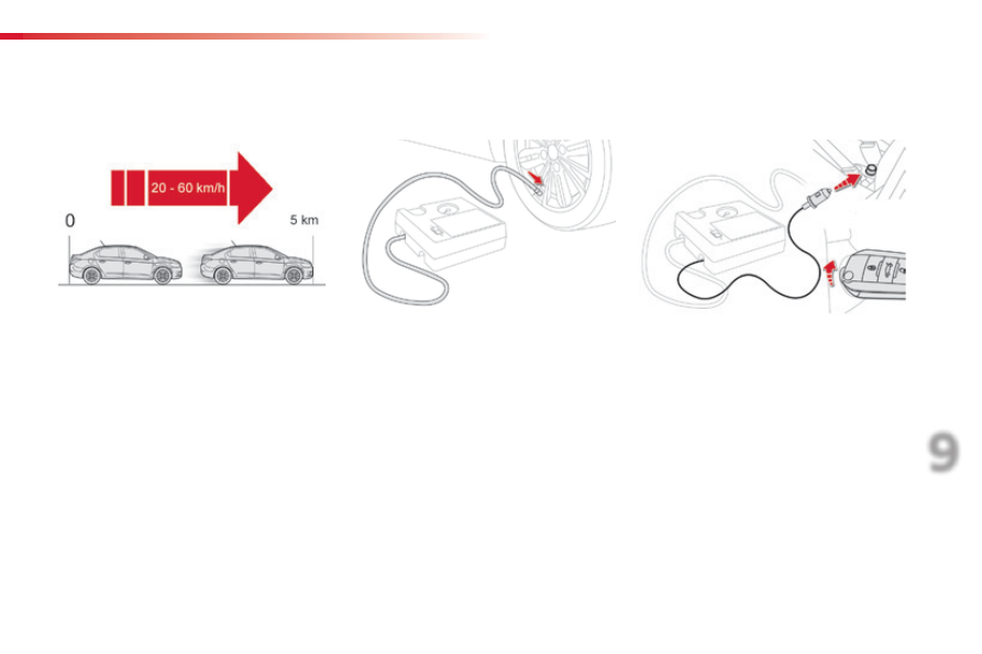
You can also use the compressor, without 
injecting sealant, to check and if necessary 
adjust the tyre pressures

F

  Check that the compressor switch is at 

the "O

" position.

F

  Uncoil fully the electric cable, stowed under 

the compressor.

F

  Connect the compressor's plug to the 

vehicle's 12 V socket.

F

  Switch on the ignition.

F  Place the switch in the "O

" position.

F

  Remove the kit.

F

  Drive immediately for approximately 

three miles (five kilometres), at reduced 
speed (between 15 and 35 mph (20 and 
60 km/h)), to plug the puncture.

F

  Stop to check the repair and the tyre 

pressure using the kit.

Checking / adjusting tyre pressures

F

  Remove the valve cap from the tyre and 

place it in a clean area.

F

  Uncoil the pipe stowed under the 

compressor.

F

  Screw the pipe onto the valve and tighten 

firmly.

144

Practical information

C-elysee_en_Chap09_info-pratiques_ed01-2016

F

  Start the compressor by placing the switch 

at the "I

" position and adjust the pressure 

to the value shown on the vehicle's tyre 
pressure label.


To deflate: press the black button on the 
compressor pipe, at the valve connector.

F

  Once the correct pressure is reached, put 

the switch to the "O

" position.

F

  Remove the kit then stow it.

Should the pressure of one or more 
tyres be adjusted, it is necessary to 
reinitialise the under-inflation detection 
system.
For more information on under-inflation 
detection, refer to the corresponding 
section.

Tyre under-inflation 

detection

After repair of the tyre, the warning 
lamp will remain on until the system is 
reinitialised.
For more information on under-inflation 
detection, refer to the corresponding 
section.

145

9

Practical information

C-elysee_en_Chap09_info-pratiques_ed01-2016

Spare wheel

The tools are installed in the boot under the 
floor.
To gain access to them:
F  open the boot,
F

  lift the floor and remove it.

F

  remove the storage box containing the 

tools.

Access to the tools

List of tools

Procedure for changing a wheel with a punctured tyre for the spare wheel using the tools provided with the vehicle.

These tools are specific to your vehicle and 
can vary according to the level of equipment. 
Do not use them for any purpose other than 
detailed below.
1.

  Wheelbrace.


For removing the wheel trim and removing 
the wheel bolts.

2.

  Jack with integral handle.


For raising the vehicle.

3.

  Wheel bolt cover removal tool.


For removing the wheel bolt cover on alloy 
wheels.

4.

  Towing eye.

For more information on towing, refer to the 
corresponding section.

The jack must only be used to change a 
wheel with a damaged tyre.

The jack does not require any 
maintenance.

The jack conforms to European 
legislation, such as defined in the 
Machinery Directive 2006/42/CE.

146

Practical information

C-elysee_en_Chap09_info-pratiques_ed01-2016

The spare wheel is installed in the boot under 
the floor.
Depending on engine, the spare wheel is 
a standard wheel or the space-saver type 
(BlueHDi 100).

Access to the spare wheel

Taking out the wheel

F

  Unclip the tool storage box (standard spare 

wheel).

F

  Unscrew the central nut.

F

  Remove the fixing parts (nut and bolt).

F

  Raise the spare wheel towards you from 

the rear.

F

  Take the wheel out of the boot.

147

9

Practical information

C-elysee_en_Chap09_info-pratiques_ed01-2016

Putting the wheel back in place

F

  Put the wheel back in its housing.

F

  Unscrew the nut a few turns on the bolt.

F

  Position the fixing parts (nut and bolt) in the 

middle of the wheel.

F

  Tighten the central nut until it clicks to 

retain the wheel correctly.

If there is no wheel in the well, the fixing 
parts (nut and bolt) cannot be refitted.

F

  Clip the tool storage box back into place 

(standard spare wheel).

148

Practical information

C-elysee_en_Chap09_info-pratiques_ed01-2016

Removing a wheel

Parking the vehicle

Immobilise the vehicle where it does not 
block traffic: the ground must be level, 
stable and not slippery.
Apply the parking brake, switch off the 
ignition and engage first gear* to block 
the wheels.
Check that the parking brake warning 
lamp in the instrument panel comes on.
The occupants must get out of the 
vehicle and wait where they are safe.
Ensure that the jack is correctly 
positioned at one of the vehicle's 
jacking points.
Incorrect use of the jack could cause 
the vehicle to drop.
Never go underneath a vehicle raised 
using a jack; use an axle stand.

List of operations

Do not use a jack other than the one 
supplied by the manufacturer.

*  Position R for an electronic gearbox; P for an 

automatic gearbox.

Wheel with wheel trim

When removing the wheel, first 

remove the wheel trim using the 
wheelbrace 1 by pulling at the valve 
aperture.

When refitting the wheel, refit the 

wheel trim, starting by placing its cutout 
in line with the valve and then pressing 
round its edge with the palm of your 
hand.

F

  Remove the wheel bolt cover using the 

tool 3

 (alloy wheels).

F

  Slacken the bolts using the wheelbrace 1 

only.

149

9

Practical information

C-elysee_en_Chap09_info-pratiques_ed01-2016

F

  Place the foot of the jack 2 on the ground 

and ensure that it is directly below the 
front A or rear 

B jacking point provided on 

the underbody, whichever is closest to the 
wheel to be changed.

F

  Extend the jack 2 until its head comes into contact with the jacking point A or 

B used; the 

vehicle’s contact surface at A or 

B must engage with the central part of the head of the jack.

F

  Raise the vehicle until there is sufficient space between the wheel and the ground to admit the 

spare (not punctured) wheel easily.

Ensure that the jack is stable. If the ground is slippery or loose, the jack might slip or drop -  
Risk of injury!
Take care to position the jack only at one of the vehicle’s jacking points A or 

B under the vehicle, 

ensuring that the contact surface of the vehicle’s jacking point is centred on the head of the jack. 
Otherwise there is a risk of damage to the vehicle and/or that the jack might drop - Risk of injury!

150

Practical information

C-elysee_en_Chap09_info-pratiques_ed01-2016

F

  Remove the bolts and store them in a clean 

place.

F

  Remove the wheel.

Fitting a wheel

Fitting the spare wheel

If your vehicle is fitted with alloy wheels, 
when tightening the bolts on fitting, it is 
normal to notice that the washers do not 
come into contact with the spare wheel. 
The wheel is secured by the conical 
surface of each bolt.

After changing a wheel

When using a "space-saver" type of 
spare wheel, do not exceed 50 mph  
(80 km/h).
Have the tightening of the bolts and the 
pressure of the spare wheel checked 
by a CITROËN dealer or a qualified 
workshop without delay.
Have the punctured wheel repaired 
and refitted to the vehicle as soon as 
possible.

Stowing the wheel with 

punctured tyre

The wheel with punctured tyre can be 
stowed under the floor, in the housing 
for the standard spare wheel.
To stow an alloy wheel, first remove the 
trim from the middle of the wheel so that 
the fixing parts (nut and bolt) can be put 
in place.
In the case of a "space-saver" type 
spare wheel, the wheel with punctured 
tyre cannot be stowed under the floor. It 
must be stowed in the boot; use a cover 
to protect the inside of the boot.

151

9

Practical information

C-elysee_en_Chap09_info-pratiques_ed01-2016

F

  Lower the vehicle fully.

F

  Fold the jack 2 and detach it.

F

  Tighten the bolts using the wheelbrace 1 

only.

F

  Refit the wheel bolt cover (alloy wheels).

F

  Stow the tools in their box.

List of operations

F

  Put the wheel in place on the hub.

F

  Screw in the bolts fully by hand.

F

  Pre-tighten the bolts using the 

wheelbrace 1

 only.

152

Practical information

C-elysee_en_Chap09_info-pratiques_ed01-2016

Snow chains

In wintry conditions, snow chains improve traction as well as the behaviour of the vehicle when 
braking.

Advice on installation

F

  If you have to fit the chains during a 

journey, stop the vehicle on a flat surface 
on the side of the road.

F

  Apply the parking brake and position any 

wheel chocks to prevent movement of your 
vehicle.

F

  Fit the chains following the instructions 

provided by the manufacturer.

F

  Move off gently and drive for a few 

moments, without exceeding 30 mph 
(50 km/h).

F

  Stop your vehicle and check that the snow 

chains are correctly tightened.

Use only the chains designed to be fitted to the 
type of wheel fitted to your vehicle:

Original  

tyre size

Maximum  

link size.

185/65 R15

9 mm

195/55 R16

For more information on snow chains, contact a 
CITROËN dealer or a qualified workshop.

It is strongly recommended that before 
you leave, you practise fitting the snow 
chains on a level and dry surface.

Avoid driving with snow chains on roads 
that have been cleared of snow, to 
avoid damaging your vehicle's tyres and 
the road surface. If your vehicle is fitted 
with alloy wheels, check that no part of 
the chain or its fixings is in contact with 
the wheel rim.

Take account of the legislation in force 
in your country on the use of snow 
chains and the maximum running speed 
authorised.

The snow chains must be fitted only 
to the front wheels. They must never 
be fitted to "space-saver" type spare 
wheels.

153

9

Practical information

C-elysee_en_Chap09_info-pratiques_ed01-2016

Changing a bulb

Front lamps

In some weather conditions (e.g. low 
temperature or humidity), the presence 
of misting on the internal surface of the 
glass of the headlamps and rear lamps 
is normal; it disappears after the lamps 
have been on for a few minutes.

The headlamps are fitted with 
polycarbonate glass with a protective 
coating:

do not clean them using a dry 

or abrasive cloth, nor with a 

detergent or solvent product,

F

  use a sponge and soapy water or a 

pH neutral product,

F

  when using a high pressure washer 

on persistent marks, do not keep 
the lance directed towards the 
lamps or their edges for too long, 
so as not to damage their protective 
coating and seals.

Changing a bulb should only be done 
after the headlamp has been switched 
off for several minutes (risk of serious 
burns).
F

  Do not touch the bulb directly with 

your fingers, use a lint-free cloth.

It is imperative to use only anti-
ultraviolet (UV) type bulbs to avoid 
damaging the headlamp.
Always replace a failed bulb with a 
new bulb with the same type and 
specification.

1. 

Direction indicators (PY21W amber).

2. 

Main beam headlamps (H1-55W).

3. 

Dipped beam headlamps (H7-55W).

4. 

Daytime running lamps / sidelamps 

(W21/5W). 

 or
 

Sidelamps (W5W).

5. 

Front foglamps (H11-55W).

154

Practical information

C-elysee_en_Chap09_info-pratiques_ed01-2016

Amber coloured bulbs, such as the 
direction indicators, must be replaced 
with bulbs of identical specifications 
and colour.
When refitting, close the protective 
cover carefully to preserve the sealing 
of the headlamp.

Rapid flashing of the direction indicator 
warning lamp (right or left) indicates the 
failure of a bulb on that side.

Changing direction indicator 

bulbs

F

  Turn the bulb holder an eighth of a turn 

anti-clockwise and extract it.

F

  Remove the bulb and change it.

To reassemble, carry out these operations in 
reverse order.

Changing main beam headlamp 

bulbs

F

  Remove the protective cover by pulling on 

the tab.

F

  Disconnect the bulb connector.

F

  Push the spring to one side to release 

the bulb.

F

  Remove the bulb and change it.

To refit, carry out these operations in reverse 
order.

155

9

Practical information

C-elysee_en_Chap09_info-pratiques_ed01-2016

Changing dipped beam 

headlamp bulbs

F

  Remove the protective cover by pulling 

the tab.

F

  Disconnect the bulb connector by lifting 

it off.

F

  Pull the bulb out and change it.

To refit, carry out these operations in reverse 
order.

Changing daytime running lamp / 

sidelamp bulbs

F

  Pull the bulb holder pressing on the tabs on 

both sides.

F

  Remove the bulb and change it.

To refit, carry out these operations in reverse 
order.

156

Practical information

C-elysee_en_Chap09_info-pratiques_ed01-2016

Changing front foglamp  

bulbs

F

  Access to the front foglamp is through the 

aperture below the bumper.


If necessary, unscrew and completely 
remove the cover.

F

  Turn the bulb holder a quarter turn anti-

clockwise and pull it out.

F

  Disconnect the bulb connector.

F

  Remove the bulb and change it.

To refit, carry out these operations in reverse 
order.

If you experience any difficulty in 
replacing bulbs, contact your CITROËN 
dealer or a qualified workshop.

Changing direction indicator side 

repeaters

F

  Insert a screwdriver towards the centre of 

the repeater between the repeater and the 
base on the body.

F

  Tilt the screwdriver to extract the repeater 

and remove it.

F

  Disconnect the repeater connector.

F

  Replace the module.

To refit, carry out these operations in reverse 
order.

Contact a CITROËN dealer or 
a qualified workshop to obtain a 
replacement side repeater module.

157

9

Practical information

C-elysee_en_Chap09_info-pratiques_ed01-2016

Changing bulbs

These bulbs are changed from inside the boot:

F  open the boot,
F

  remove the access grille from the 

corresponding side trim panel,

F

  slacken and remove the nut,

F

  disconnect the lamp unit connector,

F

  unclip the lamp unit by lowering the tongue 

and carefully extract it pulling in line 
towards the outside,

F

  remove the four screws and lift off the bulb 

holder,

F

  turn the failed bulb a quarter of a turn and 

change it.

To refit, carry out these operations in reverse 
order.
Take care to engage the lamp unit in its guides, 
while keeping it in line with the vehicle.
Tighten sufficiently to ensure sealing, but 
without damaging the lamp.

1. 

Direction indicators (PY21W amber).

2. 

Reversing lamps (R10W).

3. 

Foglamp (P21W).

4. 

Sidelamps (P21/5W).

5. 

Brake lamps / sidelamps (P21/5W).

Rear lamps

158

Practical information

C-elysee_en_Chap09_info-pratiques_ed01-2016

Third brake lamp  

(5 W5W bulbs)

Number plate lamps  

(W5W)

F

  Insert a thin screwdriver into one of the 

transparent lens.

F

  Push it outwards to unclip it and remove it.

F

  Remove the failed bulb and change it.

To reassemble, carry out these operations in 
reverse order.

Ensure that the housing cover is 
correctly positioned on its support 
before clipping it into place.

To change these bulbs, it is necessary to 
remove the housing from the rear shelf, 
working from the rear seats:
F

  pull the housing cover towards you and up 

to disengage it,

F

  disconnect the lamp connector,

F

  unclip the bulb holder by lifting the two lugs 

and remove it,

F

  replace the failed bulb.

To reassemble, carry out these operations in 
reverse order.


Content   ..  8  9  10  11   ..