RAM 2500 Diesel (2007 year). Manual - part 13
 

  Index      RAM     RAM 2500 Diesel (2007 year) - manual in english


Search            copyright infringement  


Content      ..     11      12      13      14     ..


RAM 2500 Diesel (2007 year). Manual - part 13


INSTRUMENT CLUSTER

Instrument Cluster – 5.9L Diesel Engine

196

UNDERSTANDING YOUR INSTRUMENT PANEL

-------------------------------------------------------------------------------------------------------------------------------------------------------------

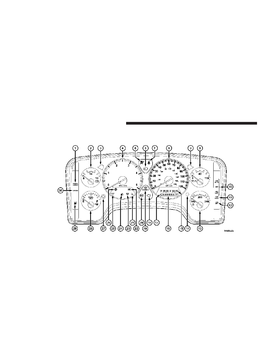
Instrument Cluster – 6.7L Diesel Engine

UNDERSTANDING YOUR INSTRUMENT PANEL

197

4

-------------------------------------------------------------------------------------------------------------------------------------------------------------

INSTRUMENT CLUSTER DESCRIPTION

1. Check Gages

This light illuminates when the Voltmeter, Engine
Oil Pressure or Engine Coolant Temperature

gages indicate a reading either too high or too low.
Examine the gages carefully, and follow the instructions
contained below for each indicated problem.

NOTE:

When the ignition switch is turned to OFF, the

Fuel Gage, Voltmeter, Oil Pressure and Engine Coolant
Temperature gages may not show accurate readings.
When the engine is not running, turn the ignition switch
to ON to obtain accurate readings.

2. Voltmeter

When the engine is running, the gauge indicates
the electrical system voltage. The pointer should

stay within the normal range if the battery is charged. If

the pointer moves to either extreme left or right and
remains there during normal driving, the electrical sys-
tem should be serviced.

NOTE:

If the gauge pointer moves to either extreme of

the gauge, the “Check Gages” indicator will illuminate
and a single chime will sound.

NOTE:

• The voltmeter may show a gauge fluctuation at vari-

ous engine temperatures. This cycling operation is
caused by the post-heat cycle of the intake manifold
heater system. The number of cycles and the length of
the cycling operation is controlled by the engine
control module. Post-heat operation can run for sev-
eral minutes, and then the electrical system and volt-
meter needle will stabilize.

• The cycling action will cause temporary dimming of

the headlamps, interior lamps, and also a noticeable
reduction in blower motor speed.

198

UNDERSTANDING YOUR INSTRUMENT PANEL

-------------------------------------------------------------------------------------------------------------------------------------------------------------

3. Turn Signal Indicators
Lights in instrument cluster flash when outside turn
signals are operating.

4. Tachometer
The tachometer indicates engine speed in revolutions per
minute.

CAUTION!

Do not operate the engine with the tachometer
pointer at high rpm for extended periods. Engine
damage may occur.

5. Airbag Indicator Light
The indicator lights and remains lit for 6 to 8 seconds
when the ignition is first turned on. If the light stays on,
flickers or comes on while driving, have the airbag
system checked by an authorized dealer.

6. High Beam Indicator

This indicator shows that headlights are on high
beam.

7. Seat Belt Reminder Light

When the ignition switch is first turned ON, this
light will turn on for 5 to 8 seconds as a bulb check.
During the bulb check, if the driver’s seat belt is

unbuckled, a chime will sound. After the bulb check or
when driving, if the driver seat belt remains unbuckled,
the Seat Belt Warning Light will flash or remain on
continuously. Refer to

⬙Enhanced Driver Seat Belt Re-

minder System (BeltAlert™)

⬙ in the Occupant Restraints

section for more information. (See page 33 for more information.)
information.)

8. Speedometer
The speedometer shows the vehicle speed in miles per
hour and/or kilometers per hour.

UNDERSTANDING YOUR INSTRUMENT PANEL

199

4

-------------------------------------------------------------------------------------------------------------------------------------------------------------

9. Oil Pressure Gauge

The pointer should always indicate some oil pres-
sure when the engine is running. A continuous

high or low reading, under normal driving conditions,
may indicate a lubrication system malfunction. Immedi-
ate service should be obtained. (See page 414 for more information.)
information.)

NOTE:

If the gauge pointer moves to either extreme of

the gauge, the “Check Gages” indicator will illuminate
and a single chime will sound.

10. Transfer Case Position
(See page 306 for more information.)

11. TOW HAUL
The TOW HAUL button is located at the end of the gear
shift lever. This light will illuminate when the TOW
HAUL button is pushed once. (See page 294 for more information.)
information.)

12. OD/OFF – IF EQUIPPED
If equipped, the OD/OFF button is located at the end of
the gear shift lever. This light will illuminate when the
TOW HAUL OD/OFF button is pushed twice. (See page
294 for more information.)

13. Temperature Gauge

The temperature gauge indicates engine coolant
temperature. Any reading within the normal
range indicates that the cooling system is operat-

ing satisfactorily. The gauge needle will likely indicate a
higher temperature when driving in hot weather, up
mountain grades, in heavy traffic, or when towing a
trailer. If the needle rises to the “245°F” mark, stop the
vehicle, shift into N (Neutral), and increase the engine
idle speed for 2 to 3 minutes. If the temperature reading
does not return to normal, shut your engine OFF and
allow it to cool. Seek authorized service immediately. See
Cooling System information in the section on “Maintain-
ing Your Vehicle.”

200

UNDERSTANDING YOUR INSTRUMENT PANEL

-------------------------------------------------------------------------------------------------------------------------------------------------------------

CAUTION!

Do not leave your vehicle unattended with the en-
gine running as you would not be able to react to the
temperature indicator if the engine overheats.

NOTE:

Engine idle speed will automatically increase to

1000 rpm at elevated coolant temperatures to improve
engine cooling.

NOTE:

If the gauge pointer moves to either extreme of

the gauge, the “Check Gages” indicator will illuminate
and a single chime will sound.

14. Security Light
The light will flash rapidly for approximately 16 seconds
when the vehicle theft alarm is arming. The light will
flash at a slower rate after the alarm is set. The security
light will also come on for about two seconds when the
ignition is first turned ON.

15. Transmission Range Indicator (Automatic
Transmissions Only)
When the gear selector lever is moved on vehicles with
the 48RE transmission, this indicator shows the auto-
matic transmission gear range selected (P R N D 2 1).

When the gear selector lever is moved on vehicles with
the 68RFE transmission, this indicator shows the auto-
matic transmission gear range selected (P R N D). Ve-
hicles equipped with Auto-6/Electronic Range Select
(ERS) will display the selection of the desired top gear, in
the position next to the D (Drive).

16. Odometer/Trip Odometer
The odometer shows the total distance the vehicle has
been driven.

If the odometer reading is changed during repair or
replacement, be sure to keep a record of the reading
before and after the service so that the correct mileage can
be determined.

UNDERSTANDING YOUR INSTRUMENT PANEL

201

4

-------------------------------------------------------------------------------------------------------------------------------------------------------------

The trip odometer shows individual trip mileage. To
toggle between the odometer and the trip odometer,
press the Odometer/Trip Odometer Button. To reset the
Trip Odometer, press and hold the button while in trip
mode, until the Trip Odometer resets.

Also the cluster will display, replacing the odometer,
vehicle warning messages such as: door, and No-fuse.

NOTE:

There is also an engine hour function. This

indicates the total number of hours the engine has been
running. To display the engine hours perform the follow-
ing: Place the ignition in RUN, but do not start the
engine. With the odometer value displayed, hold the trip
button down for a period of 6 seconds. The odometer will
change to trip value first, then it will display the engine
hour value. The engine hours will be displayed for a
period of 30 seconds until the ignition is turned off or the
engine is started.

17. Front Fog Light Indicator — If Equipped

This light shows when the front fog lights are ON.

18. Malfunction Indicator Light

This light is part of an onboard diagnostic system
which monitors the emissions and engine control
system. If the vehicle is ready for emissions

testing the light will come on when the ignition is first
turned on and remain on, as a bulb check, until the
engine is started. If the vehicle is not ready for emissions
testing the light will come on when the ignition is first
turned on and remain on for 15 seconds, then blink for 5
seconds, and remain on until the vehicle is started. If the
bulb does not come on during starting, have the condi-
tion investigated promptly.

If this light comes on and remains on while driving, it
suggests a potential engine control problem and the need
for system service.

202

UNDERSTANDING YOUR INSTRUMENT PANEL

-------------------------------------------------------------------------------------------------------------------------------------------------------------

Although your vehicle will usually be drivable and not
need towing, see your dealer for service as soon as
possible.

CAUTION!

Prolonged driving with the MIL on could cause
damage to the engine control system. It also could
affect fuel economy and driveability.

If the MIL is flashing, severe catalytic converter
damage and power loss will soon occur. Immediate
service is required.

19. Brake System Warning Light
This light illuminates when the ignition key is turned to
the ON position and remains on for a few seconds. If the
light stays on longer, it may be an indication that the
parking brake has not been released. This light will

illuminate if the brake fluid is low, especially when
braking or accelerating hard. This light will illuminate if
the ABS indicator light has a malfunction. This light will
flash if the engine is running and the parking brake is on.
If the light remains on when the parking brake is
released, it indicates a possible brake hydraulic system
malfunction. In this case, the light will remain on until
the cause is corrected.

If brake failure is indicated, immediate repair is necessary
and continued operation of the vehicle in this condition is
dangerous.

Acceleration which causes the rear wheels to slip for a
period of time may result in the red brake light illumi-
nating and a brake switch code being set on ABS
equipped vehicles. Depressing the brake pedal should
extinguish the red brake light.

UNDERSTANDING YOUR INSTRUMENT PANEL

203

4

-------------------------------------------------------------------------------------------------------------------------------------------------------------

20. ABS Warning Light

This light monitors the Anti-Lock Brake System
which is described elsewhere in this manual. This

light will come on when the ignition key is turned to the
ON position and may stay on for five seconds. If the ABS
light remains on or comes on during driving, it indicates
that the anti-lock portion of the brake system is not
functioning and that service is required. See your autho-
rized dealer immediately. The ABS light could also
illuminate during loss of traction and remain illuminated
until the brake pedal is pressed.

21. Cargo Light

The Cargo Lamp light will illuminate when the
Cargo Lamp is activated by pressing the Cargo
Light Button on the headlight switch.

22. Electronic Throttle Control (ETC)

This light informs you of a problem with the
Electronic Throttle Control system. If a prob-
lem is detected the light will come on while the
engine is running. If the light remains lit with

the engine running your vehicle will usually be drivable,
however, see your dealer for service as soon as possible.
If the light is flashing when the engine is running,
immediate service is required and you may experience
reduced performance, an elevated/rough idle or engine
stall and your vehicle may require towing. The light will
come on when the ignition is first turned on and remain
on for 15 seconds as a bulb check. If the light does not
come on during starting, have the system checked by an
authorized dealer.

204

UNDERSTANDING YOUR INSTRUMENT PANEL

-------------------------------------------------------------------------------------------------------------------------------------------------------------

23. SERV 4WD Indicator
The 4WD indicator will be illuminated whenever the
4WD mode is engaged for either the manual or electric
shift 4WD systems. The SERV 4WD indicator monitors
the electric shift 4WD system. If the SERV 4WD light
stays on or comes on during driving, it means that the
4WD system is not functioning properly and that service
is required.

24. Water In Fuel Indicator

Indicates there is water detected in the fuel
filter. Refer to the Maintenance section, Drain-
ing Fuel/Water Separator Filter, for water

drain procedure. (See page 427 for more information.)

25. Transmission Oil Temperature Warning Light
(Automatic Transmissions Only)

This light indicates that there is excessive trans-
mission fluid temperature that might occur
with severe usage such as trailer towing. It may

also occur when operating the vehicle in a high torque
converter slip condition, such as 4-wheel-drive operation
(e.g. snow plowing, off- road operation). If this light
comes on, stop the vehicle and run the engine at idle or
faster, with the transmission in NEUTRAL until the light
goes off.

26. Wait To Start Indicator

The Wait To Start Indicator will illuminate when
the ignition is turned to the run position and the

intake manifold temperature is below 66 degrees F.
Follow engine starting procedure for proper engine start-
ing and operating. Wait until the Wait To Start Indicator
turns OFF then start the vehicle.

NOTE:

The Wait To Start Indicator may not illuminate if

the engine coolant temperature is warm enough.

UNDERSTANDING YOUR INSTRUMENT PANEL

205

4

-------------------------------------------------------------------------------------------------------------------------------------------------------------

27. Odometer/Trip Odometer Button
Press this button to toggle between the odometer and the
trip odometer display. Holding the button in resets the
trip odometer reading when in trip mode.

28. Fuel Gauge
Shows level of fuel in tank when ignition switch is in the
ON position.

29. Low Fuel Warning Light

Glows when the pointer is between “E” and 1/8
indication mark (approximately 15% of tank vol-
ume) on the fuel gauge. When the fuel gauge

pointer is on “E” (equivalent to Distance To Empty [DTE]
= 0 on the overhead console if so equipped) there is

reserve fuel capacity, which corresponds to approxi-
mately 8% of tank volume. This reserve capacity was put
in place to prevent the likelihood of customers running
out of fuel when operating at maximum load conditions
in areas where there aren’t many gas stations. (See page
145 for more information.)

Ram fuel tank volumes are as follows:

• 34 gallons - 2500/3500 short box models
• 35 gallons - 2500/3500 long box models

30. CRUISE Light
This indicator lights when the electronic speed control
system is turned on.

206

UNDERSTANDING YOUR INSTRUMENT PANEL

-------------------------------------------------------------------------------------------------------------------------------------------------------------

ELECTRONIC DIGITAL CLOCK
The clock and radio each use the display panel built into
the radio. A digital readout shows the frequency and/or
time in hours and minutes (depending on your radio
model) whenever the ignition switch is in the “ON” or
“ACC” position.

When the ignition switch is in the “OFF” position, or
when the radio frequency is being displayed, time keep-
ing is accurately maintained.

On the RAQ radio the time button alternates the location
of the time and frequency on the display. On the REF only
one of the two, time or frequency is displayed at a time.

Clock Setting Procedure

1. Press and hold the time button until the hours blink.

2. Adjust the hours by turning the right side Tune /
Audio control.

3. After the hours are adjusted, press the right side Tune
/ Audio control to set the minutes.

4. Adjust the minutes using the right side Tune / Audio
control.

5. To exit, press any button/knob or wait approximately
5 seconds.

RADIO GENERAL INFORMATION

Radio Broadcast Signals
Your new radio will provide excellent reception under
most operating conditions. Like any system, however, car
radios have performance limitations, due to mobile op-
eration and natural phenomena, which might lead you to
believe your sound system is malfunctioning. To help
you understand and save you concern about these “ap-
parent” malfunctions, you must understand a point or
two about the transmission and reception of radio sig-
nals.

UNDERSTANDING YOUR INSTRUMENT PANEL

207

4

-------------------------------------------------------------------------------------------------------------------------------------------------------------

Two Types of Signals
There are two basic types of radio signals... AM or
Amplitude Modulation, in which the transmitted sound
causes the amplitude, or height, of the radio waves to
vary... and FM or Frequency Modulation, in which the
frequency of the wave is varied to carry the sound.

Electrical Disturbances
Radio waves may pick up electrical disturbances during
transmission. They mainly affect the wave amplitude,
and thus remain a part of the AM reception. They
interfere very little with the frequency variations that
carry the FM signal.

AM Reception
AM sound is based on wave amplitude, so AM reception
can be disrupted by such things as lightning, power lines
and neon signs.

FM Reception
Because FM transmission is based on frequency varia-
tions, interference that consists of amplitude variations
can be filtered out, leaving the reception relatively clear,
which is the major feature of FM radio.

NOTE:

The radio, steering wheel radio controls (if

equipped), and 6 disc CD/DVD changer (if equipped)
will remain active for up to 10 minutes after the ignition
switch has been turned off. Opening a vehicle front door
will cancel this feature.

208

UNDERSTANDING YOUR INSTRUMENT PANEL

-------------------------------------------------------------------------------------------------------------------------------------------------------------

SALES CODE REF — AM/FM/CD (SINGLE DISC)
RADIO WITH OPTIONAL SATELLITE RADIO AND
HANDS FREE PHONE CAPABILITY

NOTE:

The radio sales code is located on the lower right

side of your radio faceplate.

Operating Instructions - Radio Mode

NOTE:

The ignition switch must be in the ON or ACC

position to operate the radio.

Power Switch/Volume Control (Rotary)
Press the ON/VOL control to turn the radio ON. Press
the ON/VOL a second time to turn OFF the radio.

Electronic Volume Control
The electronic volume control turns continuously (360
degrees) in either direction without stopping. Turning the
volume control to the right increases the volume and to
the left decreases it.

When the audio system is turned on, the sound will be
set at the same volume level as last played.

For your convenience, the volume can be turned down,
but not up, when the audio system is off and the ignition
is ON.

REF Radio

UNDERSTANDING YOUR INSTRUMENT PANEL

209

4

-------------------------------------------------------------------------------------------------------------------------------------------------------------

Mode Button (Radio Mode)
Press the mode button repeatedly to select between the
CD player and Satellite Radio (if equipped).

SEEK Button (Radio Mode)
Press and release the SEEK button to search for the next
listenable station in either AM/FM or Satellite (if
equipped) mode. Press the right side of the button to seek
up and the left side to seek down. The radio will remain
tuned to the new station until you make another selec-
tion. Holding the button will bypass stations without
stopping until you release it.

MUTE Button (Radio Mode)
Press the MUTE button to cancel the sound from the
speakers.

⬙MUTE⬙ will display. Press the MUTE button a

second time and the sound from the speakers will return.
Rotating the volume control, turning the radio ON/OFF,
or turning ON/OFF the ignition, will cancel the MUTE
feature.

NOTE:

In Hands Free Phone (if equipped) mode, the

MUTE button mutes the microphone.

SCAN Button (Radio Mode)
Pressing the SCAN button causes the tuner to search for
the next listenable station in either, AM, FM, or Satellite
(if equipped) frequencies, pausing for 5 seconds at each
listenable station before continuing to the next. To stop
the search, press SCAN a second time.

PSCAN Button (Radio Mode)
Pressing the PSCAN button causes the tuner to scan
through preset stations in either, AM, FM, or Satellite (if
equipped) frequencies, pausing for 5 seconds at each
preset station before continuing to the next. To stop the
search, press PSCAN a second time.

Time Button
Press the time button and the time of day will display for
5 seconds.

210

UNDERSTANDING YOUR INSTRUMENT PANEL

-------------------------------------------------------------------------------------------------------------------------------------------------------------

Clock Setting Procedure

1. Press and hold the time button until the hours blink.

2. Adjust the hours by turning the right side Tune/
Audio control.

3. After the hours are adjusted, press the right side
Tune/Audio control to set the minutes. The minutes will
begin to blink.

4. Adjust the minutes using the right side Tune/Audio
control.

5. To exit, press any button/knob or wait 5 seconds.

RW/FF (Radio Mode)
Pressing the rewind/fast forward button causes the tuner
to search for the next frequency in the direction of the
arrows. This feature operates in either AM, FM or Satel-
lite (if equipped) frequencies.

TUNE Control (Radio Mode)
Turn the right side rotary control clockwise to increase or
counter-clockwise to decrease the frequency.

AM/FM Button (Radio Mode)
Press the button to select AM or FM Modes.

Setting the Tone, Balance, and Fade
Press the rotary TUNE control and BASS will display.
Turn the TUNE control to the right or left to increase or
decrease the Bass tones.

Press the rotary TUNE control a second time and MID
will display. Turn the TUNE control to the right or left to
increase or decrease the Mid Range tones.

Press the rotary TUNE control a third time and TREB will
display. Turn the TUNE control to the right or left to
increase or decrease the Treble tones.

UNDERSTANDING YOUR INSTRUMENT PANEL

211

4

-------------------------------------------------------------------------------------------------------------------------------------------------------------


Content      ..     11      12      13      14     ..