Chrysler Town, Dodge Caravan. Manual - part 355
(3) Unsnap the upper shroud from the lower on
the right side as follows:
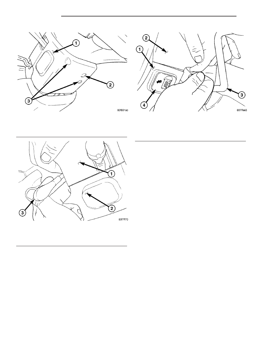
(a) Hook a finger on the right hand around the
rear of the shrouds at the seam (Fig. 34), near the
snap points.
(b) Grasp the upper shroud at the rear using the
left hand (Fig. 34).
(c) As the right hand’s hooked finger is pulled
outward against the seam, pull the upper shroud
upward using the left hand, disconnecting the
shroud snaps.
(4) Lift the upper shroud straight up off the steer-
ing column. If vehicle is equipped with traction con-
trol, disconnect wiring connector at traction control
switch pig tail. Remove upper shroud.
(5) Remove the lower shroud-to-column mounting
screw (Fig. 32).
(6) Remove the lower shroud from the steering col-
umn.
(7) If the vehicle is equipped with adjustable ped-
als:
(a) Disconnect wiring connector at adjustable
pedals switch.
(b) Depress retaining tabs on top and bottom of
switch and remove switch from lower shroud.
INSTALLATION
(1) If the vehicle is equipped with adjustable ped-
als:
(a) Install the switch into the lower shroud,
snapping it into place.
(b) Connect
wiring
harness
to
connector
at
adjustable pedals switch.
(2) Position the lower shroud under the steering
column
and
install
the
lower
shroud-to-column
mounting screw (Fig. 32). Tighten the screw to 2 N·m
(17 in. lbs.) torque.
(3) Place the upper shroud over the lower, aligning
the snap clips and alignment tabs. If the vehicle is
equipped with traction control, connect the wiring
connector at the traction control switch pig tail
before lining the shrouds up to one another.
(4) Snap the upper shroud to the lower shroud.
Once snapped into place, verify there are no gaps
between the two mating surfaces of the shrouds.
(5) Install
the
two
shroud-to-shroud
mounting
screws (Fig. 32). Tighten the screws to 2 N·m (17 in.
lbs.) torque.
(6) Ensure that the shrouds are snug and fit is
acceptable.
Fig. 32 Shroud Mounting Screw Location
1 - LOWER SHROUD
2 - LOWER SHROUD-TO-COLUMN SCREW
3 - SHROUD-TO-SHROUD SCREWS
Fig. 33 Hands Positioned To Release Left Side
1 - UPPER SHROUD
2 - LOWER SHROUD
3 - TILT LEVER
Fig. 34 Hands Positioned To Release Right Side
1 - LOWER SHROUD
2 - UPPER SHROUD
3 - SHIFT LEVER
4 - ADJUSTABLE PEDALS SWITCH (IF EQUIPPED)
19 - 22
COLUMN
RS
SHROUD - LOWER (Continued)