Chrysler Town, Dodge Caravan. Manual - part 19


  Index      Chrysler     Chrysler TOWN & COUNTRY, VOYAGER, Dodge Caravan - service repair manual 2001-2007 year


Search            


Content   ..  17  18  19  20   ..


Chrysler Town, Dodge Caravan. Manual - part 19


(8) Raise the under-hoist utility jack or transmis-

sion jack, guiding the forward mounting bracket into
place against the body. It may help to use a drift
punch placed through the hole centered between the
mounting bolt holes in the bracket and the pilot hole
in the body of the vehicle as a guide. When the four
mounting bolt holes line up with their threads in the
body, Install the mounting bolts (Fig. 3). Tighten the
four mounting bolts to 61 N·m (45 ft. lbs.) torque.

(9) Raise or lower the jack until shock absorber

lower eye aligns with threads in axle housing. Install
shock absorber lower mounting bolt. Do not fully
tighten bolt at this time.

(10) Lower the vehicle and remove hoist arms and

block of wood from under vehicle.

(11) Tighten the spring front pivot bolt to 156 N·m

(115 ft. lbs.) torque.

(12) Tighten the lower shock absorber mounting

bolt to 88 N·m (65 ft. lbs.) torque.

HUB / BEARING

DESCRIPTION

The rear wheel bearing and rear wheel hub of this

vehicle are a one-piece sealed unit, or hub and bear-
ing unit type assembly (Unit III). The hub and bear-
ing is mounted to the center of the rear axle using 4

mounting bolts. It has five wheel mounting studs on
the hub flange.

All-Wheel-Drive vehicles have a hub and bearing

unit with a splined hole in the center of the hub for
rear driveshaft stub axle acceptance.

Front-Wheel-Drive vehicles with antilock brakes

have an internally mounted wheel speed sensor and
tone wheel. This hub and bearing can be identified
by the rounded cap and molded in connector on the
rear of the assembly (Fig. 7). The sensor and tone
wheel cannot be serviced separately from the hub
and bearing.

OPERATION

The hub and bearing has internal bearings that

allow the hub to rotate with the tire and wheel
assembly (and driveshaft on All-Wheel-Drive vehi-
cles). The five wheel mounting studs mount the tire
and wheel assembly, and disc brake rotor or brake
drum to the vehicle.

On All-Wheel-Drive vehicles, the splined mating of

the driveshaft stub axle and hub allows the drive-
shaft to rotate with the hub and wheel.

Front-Wheel-Drive vehicles equipped with antilock

brakes have a wheel speed sensor and tone wheel
mounted to the rear of the hub and bearing. The tone
wheel rotates with the hub which is sensed by the
wheel speed sensor.

DIAGNOSIS AND TESTING - HUB AND
BEARING

The bearing contained in the hub and bearing

assembly will produce noise and vibration when worn
or damaged. The noise will generally change when
the bearings are loaded. A road test of the vehicle is
normally required to determine the location of a
worn or damaged bearing.

Find a smooth level road surface and bring the

vehicle up to a constant speed. When vehicle is at a

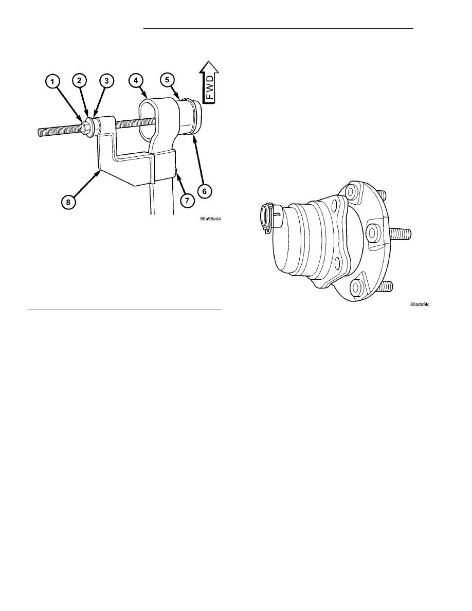
Fig. 6 TOOL 8459 MOUNTED FOR BUSHING

INSTALLATION

1 - NUT
2 - WASHER
3 - BEARING
4 - LEAF SPRING EYE
5 - BUSHING
6 - INSTALLER PLATE (8459-3)
7 - PIN
8 - BODY (8459-1)

Fig. 7 Hub And Bearing - FWD With ABS

2 - 30

REAR SUSPENSION

RS

BUSHINGS (Continued)

constant speed, swerve the vehicle back and forth
from the left and to the right. This will load and
unload the bearings and change the noise level.
When bearing damage is slight, the noise is some-
times noticeable at lower speeds and at other times
is more noticeable at speeds above 105 km/h (65
mph).

REMOVAL

FRONT-WHEEL-DRIVE VEHICLES

(1) Raise vehicle. (Refer to LUBRICATION &

MAINTENANCE/HOISTING - STANDARD PROCE-
DURE)

(2) Remove wheel and tire. (Refer to 22 - TIRES/

WHEELS - REMOVAL)

(3) Remove brake drum or disc brake caliper and

rotor from hub and bearing. (Refer to 5 - BRAKES/
HYDRAULIC/MECHANICAL/DRUM

-

REMOVAL-

)(Refer to 5 - BRAKES/HYDRAULIC/MECHANICAL/
ROTOR - REMOVAL)

(4) If equipped with antilock brakes, perform the

following:

(a) Remove secondary (yellow) retaining clip at

rear of wheel speed sensor head (Fig. 8).

(b) Push up on metal retaining clip (Fig. 8) until

it bottoms. This will release wheel speed sensor
head from hub and bearing.

(c) While holding metal clip up, pull back on

wheel speed sensor head removing it from hub and
bearing.

(5) Remove the 4 bolts attaching the hub and bear-

ing to the rear axle.

CAUTION: Corrosion may occur between the hub
and bearing, and the axle. If this occurs the hub

and bearing will be difficult to remove from the
axle. If the hub and bearing will not come out of the
axle by pulling on it by hand, do not pound on the
hub and bearing to remove it from the axle. Damage
will occur. Use the following procedure.

(6) If the hub and bearing cannot be removed from

the axle by hand, use Remover, Special Tool 8458
(Fig. 9) and the following procedure to press the hub
and bearing out of the axle.

(a) Remove the two outboard spring plate bolts.
(b) Thread Threaded Guide Pins into hub and

bearing mounting bolt holes.

(c) Using the spring plate bolts, install the

Screw Mount, Special Tool 8458–2, as shown (Fig.
9). Mount the Screw Mount to the spring plate
with the tool number facing the hub and bearing
and the beveled edge on the bottom facing the
spring, otherwise the Forcing Screw will rub the
spring plate when installed.

(d) Place Push Plate, Special Tool 8458–1, on

ends of Threaded Guide Pins

(e) Place a dab of grease in dimple of Push

Plate.

(f) Install Forcing Screw, Special Tool 8458–3,

through Screw Mount from rear.

(g) Tighten the Forcing Screw up against dimple

in Push Plate and press hub and bearing out of
axle by continuing to tighten screw.

(h) Remove the tool.

Fig. 8 Sensor Connector At Hub And Bearing

1 - SECONDARY SENSOR RETAINING CLIP
2 - METAL SENSOR RETAINING CLIP
3 - HUB AND BEARING

Fig. 9 Removal Using Special Tool 8458

1 - THREADED GUIDE PINS 8458-4
2 - HUB AND BEARING
3 - LEAF SPRING PLATE
4 - FORCING SCREW 8458-3
5 - SCREW MOUNT 8458-2
6 - PUSH PLATE 8458-1

RS

REAR SUSPENSION

2 - 31

HUB / BEARING (Continued)

(i) Reinstall the two outboard spring plate bolts.

Tighten the bolts to 102 N·m (75 ft. lbs.) torque.
(7) Remove the hub/bearing from the rear axle and

brake support plate.

ALL-WHEEL-DRIVE VEHICLES

(1) Set the parking brake. The parking brake is

set to keep the hub and bearing, and axle shaft
from rotating when loosening the hub nut.

(2) Raise vehicle. (Refer to LUBRICATION &

MAINTENANCE/HOISTING - STANDARD PROCE-
DURE)

(3) Remove the wheel/tire assembly. (Refer to 22 -

TIRES/WHEELS - REMOVAL)

(4) Remove the cotter pin and nut retainer (Fig.

18) from the stub shaft of the outer C/V joint.

(5) Remove the spring washer (Fig. 17) from the

stub shaft of the outer C/V joint.

(6) Remove the hub nut and washer (Fig. 16) from

the stub shaft of the outer C/V joint.

(7) Remove the 6 bolts mounting the driveshaft

inner joint to the output shaft of the rear drive line
module.

(8) Remove the rear wheel speed sensor (Fig. 19)

from the rear hub/bearing.

(9) Release the parking brake.
(10) Remove the disc brake caliper to adapter

guide pin bolts (Fig. 15).

(11) Remove rear caliper from adapter using the

following procedure. First rotate front of caliper up
from the adapter. Then pull the rear of the caliper
and the outboard brake shoe anti-rattle clip out from
under the rear abutment on the adapter (Fig. 14).

(12) Support caliper to prevent the weight of the

caliper from damaging the flexible brake hose (Fig.
10).

(13) Remove the rotor from the hub/bearing.
(14) Remove driveshaft from rear drive line mod-

ule and hub/bearing. Driveshaft is removed by first
compressing the inner joint on the driveshaft and
removing it from the drive line module. Then, slide
the outer joint of the driveshaft out of the hub/bear-
ing.

(15) Remove the hub/bearing to axle mounting

bolts (Fig. 13).

CAUTION: Corrosion may occur between the hub/
bearing and the axle. If this occurs the hub/bearing
will be difficult to remove from the axle. If the hub/
bearing will not come out of the axle by pulling on
it by hand, do not pound on the hub/bearing to
remove it from the axle. Pounding on the hub/bear-
ing to remove it from the axle will damage the hub/
bearing. This damage will result in noise or failure
of the hub/bearing. To remove a hub/bearing which
is corroded to the axle, lightly tap the disc brake
caliper adapter using a soft faced hammer. This will

remove both the disc brake caliper adapter and
hub/bearing from the axle. The hub/bearing will
then need to be removed from the caliper adapter.

(16) Remove the hub/bearing from the axle. (Fig.

12).

(17) If the disc brake caliper adapter and hub/

bearing were removed as an assembly from the axle
and the hub/bearing cannot be removed from the
adapter by hand, use the following procedure to
remove it from the adapter. With a helper supporting
the caliper adapter in his hands, position Remover,
Special Tool 8214-1 on the cast housing of hub/bear-
ing (Fig. 11). Do not position special tool on
inner race of hub/bearing. 
Lightly strike Remover,
Special Tool 8214-1 with a hammer to remove the
hub/bearing from the caliper adapter.

INSTALLATION

FRONT-WHEEL-DRIVE VEHICLES

(1) Install the 4 hub and bearing to axle mounting

bolts into the holes in the flange of the rear axle.

(2) Install the rear brake support plate on the 4

mounting bolts installed in the flange of the rear
axle.

(3) Align the rear hub and bearing with the 4

mounting bolts and start mounting bolts into hub
and bearing. Tighten the 4 bolts in a crisscross pat-
tern until the hub and bearing and brake support
plate is fully and squarely seated onto flange of rear
axle. Tighten the 4 mounting bolts to a torque of 129
N·m (95 ft. lbs.)

Fig. 10 Correctly Supported Caliper

1 - WIRE
2 - CALIPER
3 - ADAPTER
4 - ROTOR
5 - INNER FENDER

2 - 32

REAR SUSPENSION

RS

HUB / BEARING (Continued)

NOTE: If equipped with antilock brakes, make sure
wheel speed sensor stays clean and dry as it is
installed into the hub and bearing cap.

(4) If the vehicle is equipped with antilock brakes,

perform the following:

(a) If metal sensor retaining clip is not in the

neutral installed position on hub and bearing cap,
install from the bottom, if necessary, and push clip
upward until it snaps into position.

(b) Install wheel speed sensor head into rear of

hub and bearing aligning index tab with the notch
in the top of the mounting hole. Push the sensor in
until it snaps into place on the metal retaining
clip.

(c) Install secondary (yellow) retaining clip over

wheel speed sensor head and engage the tabs on
each side (Fig. 8).
(5) Install brake drum or disc brake rotor and

brake caliper. (Refer to 5 - BRAKES/HYDRAULIC/
MECHANICAL/DRUM - INSTALLATION)(Refer to 5
-

BRAKES/HYDRAULIC/MECHANICAL/ROTOR

-

INSTALLATION)

(6) Install wheel and tire (Refer to 22 - TIRES/

WHEELS - INSTALLATION). Tighten the wheel
nuts in the proper sequence to a torque of 135 N·m
(100 ft. lbs.).

(7) Adjust the rear brakes as necessary. (Refer to 5

-

BRAKES/HYDRAULIC/MECHANICAL/BRAKE

PADS/SHOES - ADJUSTMENTS)

(8) Lower vehicle.
(9) Road test vehicle to ensure proper operation of

brakes.

ALL-WHEEL-DRIVE VEHICLES

(1) Install hub/bearing on end of axle. (Fig. 12).

(2) Install the hub/bearing mounting bolts. In a

progressive crisscross pattern, tighten the 4 hub/
bearing mounting bolts (Fig. 13) until the disc brake
caliper adapter and hub/bearing are squarely seated
against the axle. Then tighten the hub/bearing
mounting bolts to a torque of 129 N·m (95 ft. lbs.).

(3) Install driveshaft in hub/bearing and on output

shaft

of

rear

drive line module.

Driveshaft

is

installed by first sliding the outer joint of the drive-
shaft into the hub/bearing and then compressing the

Fig. 11 Hub/Bearing Removal From Caliper Adapter

1 - SPECIAL TOOL 8214-1
2 - PARK BRAKE CABLE
3 - DISC BRAKE CALIPER ADAPTER
4 - HUB/BEARING

Fig. 12 Hub/Bearing Removal And Installation

1 - PARK BRAKE BRAKE SHOE
2 - HUB/BEARING
3 - PARK BRAKE BRAKE SHOE

Fig. 13 Hub/Bearing Mounting Bolts

1 - HUB/BEARING
2 - AXLE
3 - MOUNTING BOLTS
4 - CALIPER ADAPTER

RS

REAR SUSPENSION

2 - 33

HUB / BEARING (Continued)


Content   ..  17  18  19  20   ..