Chrysler RG Voyager. Manual - part 954
CONNECTING ROD BEARINGS
STANDARD PROCEDURE - MEASURING
CONNECTING ROD BEARING CLEARANCE
The bearing caps are not interchangeable and
should be marked at removal to ensure correct
assembly. The bearing shells must be installed with
the tangs inserted into the machined grooves in the
rods and caps. Install cap with the tangs on the same
side as the rod. Fit all rods on one bank until com-
plete. Connecting rod bearings are available in the
standard size and the following undersizes: 0.025
mm (0.001 in.) and 0.250 mm (0.010 in.).
CAUTION: Install the bearings in pairs. Do not use a
new bearing half with an old bearing half. Do not
file the rods or bearing caps.
Measure connecting rod journal for taper and out-
of-round. (Refer to 9 - ENGINE/ENGINE BLOCK/
CRANKSHAFT - INSPECTION)
The connecting rod bearing clearances can be
determined by use of Plastigage or the equivalent.
The following is the recommended procedure for the
use of Plastigage:
(1) Rotate the crankshaft until the connecting rod
to be checked is at the bottom of its stroke.
(2) Remove oil film from surface to be checked.
Plastigage is soluble in oil.
(3) Place a piece of Plastigage across the entire
width of the bearing shell in the bearing cap approx-
imately 6.35 mm (1/4 in.) off center and away from
the oil hole. In addition, suspect areas can be
checked by placing Plastigage in that area.
(4) Assemble the rod cap with Plastigage in place.
Tighten the rod cap to the specified torque. Do not
rotate the crankshaft while assembling the cap
or the Plastigage may be smeared, giving inac-
curate results.
(5)
Remove the bearing cap and compare the
width of the flattened Plastigage with the scale pro-
vided on the package (Fig. 63). Locate the band clos-
est to the same width. This band indicates the
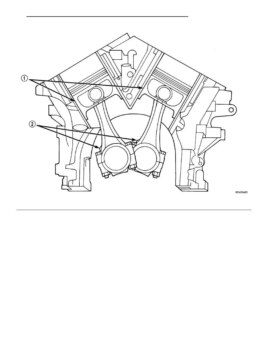
Fig. 62 Piston and Connecting Rod Positioning (Front View of Engine)
1 - MAJOR THRUST SIDE OF PISTON
2 - OIL SQUIRT HOLE
RS
ENGINE 3.3/3.8L
9 - 125
PISTON & CONNECTING ROD (Continued)