Chrysler RG Voyager. Manual - part 754


  Index      Chrysler     Chrysler RG Voyager - service repair manual 2005 year


Search            


Content   ..  752  753  754  755   ..


Chrysler RG Voyager. Manual - part 754


WARNING: When carrying or handling an unde-
ployed airbag, the trim side of the airbag should be
pointing toward the body to minimize the possibility
of injury if accidental deployment occurs. Do not
place undeployed airbag face down on a solid sur-
face, the airbag will propel into the air if accidental
deployment occurs. Failure to do this may result in
personal injury or death.

INSTALLATION

DEPLOYED AIRBAG

(1) Perform clean up procedure (Refer to 8 - ELEC-

TRICAL/RESTRAINTS - STANDARD PROCEDURE
- SERVICE AFTER AN AIRBAG DEPLOYMENT).

(2) Install a new steering column assembly and

lower steering column coupler (Refer to 19 - STEER-
ING/COLUMN - INSTALLATION).

(3) Install the new clockspring.
(4) Connect

the

4-way

and

6-way

connectors

between the clockspring and the instrument panel
wiring harness.

(5) Install the steering column shrouds and con-

nect traction control wire connector (if equipped)
(Refer

to

19

-

STEERING/COLUMN/LOWER

SHROUD - INSTALLATION).

(6) Install the steering wheel (Refer to 19 -

STEERING/COLUMN/STEERING

WHEEL

-

INSTALLATION).

(7) Connect the 4–way harness connector to the

speed control/horn harness to the clockspring.

(8) Connect the 2–way connector to the remote

radio control harness.

(9) Install the driver airbag and the two screws

retaining the airbag. Tighten screws to 10 N·m (90
in. lbs.)

WARNING: Do not connect the battery negative
cable (Refer to 8 - ELECTRICAL/RESTRAINTS -
DIAGNOSIS AND TESTING - AIRBAG SYSTEM). Per-
sonal injury or death may result if the system test
is not performed first.

UNDEPLOYED AIRBAG

(1) Connect the harness connector on the driver

airbag trim cover (horn, speed controls) to the clock-
spring.

(2) Connect the squib connectors to the driver air-

bag.

(3) Position the driver airbag into the steering

wheel.

(4) Install the two screws retaining the airbag.

Tighten screws to 10 N·m (90 in. lbs.)

WARNING: Do not connect the battery negative
cable (Refer to 8 - ELECTRICAL/RESTRAINTS -
DIAGNOSIS AND TESTING - AIRBAG SYSTEM). Per-
sonal injury or death may result if the system test
is not performed first.

IMPACT SENSOR

DESCRIPTION

FRONT IMPACT SENSORS

There are two front impact sensors (Fig. 21), one

on the left, and one on the right front sides of the
vehicle. These sensors are mounted remotely from
the impact sensor that is internal to the Occupant
Restraint Controller (ORC). The right and left front
and side impact sensors are identical in construction
and calibration and each front impact sensor is

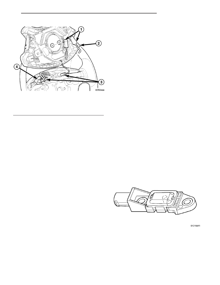
Fig. 20 DRIVER AIRBAG WIRE CONNECTIONS

1 - AIRBAG SQUIB CONNECTORS
2 - DRIVER AIRBAG
3 - HORN/SPEED CONTROL CONNECTOR
4 - CLOCK SPRING

Fig. 21 FRONT IMPACT SENSOR

RS

RESTRAINTS

8O - 17

DRIVER AIRBAG (Continued)

secured with two screws. The front impact sensors
are secured with two screws to the outboard sides of
the right and left front rail tips.

The impact sensor housing has an integral connec-

tor and two mounting ears, each with a metal sleeve
to provide crush protection. A cavity in the center of
the molded black plastic impact sensor housing con-
tains the electronic circuitry of the sensor which
includes an electronic communication chip and an
electronic impact sensor. Potting material fills the
cavity to seal and protect the internal electronic cir-
cuitry and components. The front impact sensors are
each connected to the vehicle electrical system
through the headlamp to dash wire harness.

The front impact sensors cannot be repaired or

adjusted and, if damaged or faulty, they must be
replaced. If a front impact sensor is faulty, only the
sensor needs to be replaced. If the sensor is damaged
or faulty, or if proper tightening torque of the screws
that secure the sensor to the bracket cannot be
achieved, the sensor and bracket must be replaced.
Refer to the proper body diagnostic information for
diagnosis and testing.

SIDE IMPACT SENSORS

Three side impact sensors (Fig. 22) are used on

each side of the vehicle. These sensors are mounted
remotely from the bi-directional safing sensor that is
internal to the Occupant Restraint Controller (ORC).
The side and front impact sensors are identical in
construction and calibration and each impact sensor
is secured with two screws. Each side impact sensor
is secured with two screws. The first row side impact

sensor is located in the B-pillar, just above the front
seat belt retractor (Fig. 23). The second row side
impact sensor is located in the sliding door opening,
in the lower door track area (Fig. 23). The third row
side impact sensor is located behind the quarter trim
panel, above the rear tire wheel well, between the C
and D-pillars (Fig. 23).

The impact sensor housing has an integral connec-

tor. A cavity in the center of the molded black plastic
impact sensor housing contains the electronic cir-
cuitry of the sensor which includes an electronic com-
munication chip and an electronic impact sensor.

Fig. 23 SIDE IMPACT SENSOR LOCATION

1 - FRONT ROW SIDE IMPACT SENSOR

3 - THIRD ROW SIDE IMPACT SENSOR

2 - SECOND ROW SIDE IMPACT SENSOR

Fig. 22 SIDE IMPACT SENSOR

8O - 18

RESTRAINTS

RS

IMPACT SENSOR (Continued)

Potting material fills the cavity to seal and protect
the internal electronic circuitry and components. The
side impact sensors are each connected to the vehicle
electrical system through a connector of the body
harness.

The side impact sensors cannot be repaired or

adjusted.

If

damaged

or

faulty,

they

must

be

replaced. Refer to the proper body diagnostic infor-
mation for diagnosis and testing.

REMOVAL

FRONT IMPACT SENSOR

The right and left front impact sensors are

mounted identically on the front rail tips.

(1) Open hood, disconnect and isolate the battery

negative cable.

WARNING: Wait two minutes for the airbag system
reserve capacitor to discharge before beginning
any airbag system or component service. Failure to
do so may result in accidental airbag deployment,
personal injury or death.

(2) Hoist vehicle.
(3) Disconnect electrical connector (Fig. 24).
(4) Remove the two screws attaching front impact

sensor to outer rails (Fig. 24).

(5) Remove sensor from vehicle.

SIDE IMPACT SENSORS

B-PILLAR MOUNTED

The right and left front row side impact sensors,

are mounted identically, on opposite sides of the vehi-
cle, in the b-pillar.

(1) Open hood, disconnect and isolate the battery

negative cable.

WARNING: Wait two minutes for the system reserve
capacitor to discharge before beginning any airbag
component service. Personal injury or death may
result.

(2) Remove the B-pillar lower trim for the side of

the vehicle that you are replacing the side impact
sensor (Refer to 23 - BODY/INTERIOR/B-PILLAR
LOWER TRIM - REMOVAL).

(3) Disconnect the electrical connector from the

impact sensor (Fig. 25).

(4) Remove the four retaining screws to the impact

sensor bracket (Fig. 25).

(5) Remove impact sensor from vehicle (Fig. 26).

SLIDING DOOR OPENING MOUNTED

The right and left second row side impact sensors,

are mounted identically, on opposite sides of the vehi-
cle, in the sliding door opening lower rear where the
lower roller arm mounts in the lower door track.

Fig. 24 FRONT IMPACT SENSOR REMOVE/INSTALL

1 - FRONT IMPACT SENSOR WIRE HARNESS RETAINER
2 - FRONT IMPACT SENSOR RETAINING SCREW
3 - FRONT IMPACT SENSOR WIRE HARNESS
4 - FRONT IMPACT SENSOR
5 - LOWER RADIATOR SUPPORT

Fig. 25 FRONT ROW SIDE IMPACT SENSOR AND

BRACKET

1 - B-PILLAR
2 - FRONT ROW SIDE IMPACT SENSOR ELECTRICAL
CONNECTOR
3 - FRONT ROW SIDE IMPACT SENSOR AND MOUNTING
BRACKET
4 - FRONT ROW SIDE IMPACT SENSOR RETAINING SCREW

RS

RESTRAINTS

8O - 19

IMPACT SENSOR (Continued)

(1) Open hood, disconnect and isolate the battery

negative cable.

WARNING: Wait two minutes for the system reserve
capacitor to discharge before beginning any airbag
component service. Personal injury or death may
result.

(2) Open sliding door to the fullest open position.
(3) Remove the two retaining screws to the impact

sensor (Fig. 27).

(4) Disconnect the electrical connector from the

impact sensor and remove from vehicle (Fig. 27).

QUARTER PANEL MOUNTED

(1) Open hood, disconnect and isolate the battery

negative cable.

WARNING: Wait two minutes for the system reserve
capacitor to discharge before beginning any airbag
component service. Personal injury or death may
result.

(2) Remove the quarter trim panel for the side of

the vehicle that you are replacing the side impact
sensor (Refer to 23 - BODY/INTERIOR/QUARTER
TRIM PANEL - REMOVAL).

(3) Remove the two retaining screws to the impact

sensor (Fig. 28).

(4) Disconnect the electrical connector from the

impact sensor and remove from vehicle (Fig. 28).

INSTALLATION

FRONT IMPACT SENSOR

(1) Position sensor in vehicle (Fig. 24).
(2) Install the two retaining screws to the impact

sensor (Fig. 24). Torque screws to 7 N·m (62 in. lbs.).

(3) Connect electrical connector (Fig. 24).
(4) Lower vehicle from hoist.

Fig. 26 FRONT ROW SIDE IMPACT SENSOR/

BRACKET

1 - FRONT ROW SIDE IMPACT SENSOR
2 - SENSOR TO BRACKET ATTACHMENT
3 - FRONT ROW SIDE IMPACT SENSOR MOUNTING BRACKET

Fig. 27 2ND ROW SIDE IMPACT SENSOR

1 - 2ND ROW SIDE IMPACT SENSOR ELECTRICAL CONNECTOR
2 - 2ND ROW SIDE IMPACT SENSOR RETAINING SCREWS
3 - SLIDING DOOR LOWER ROLLER ARM

Fig. 28 3RD ROW SIDE IMPACT SENSOR

1 - 3RD ROW SIDE IMPACT SENSOR
2 - 3RD ROW SIDE IMPACT SENSOR MOUNTING SCREWS
3 - REAR SPEAKER
4 - REAR WHEEL WELL

8O - 20

RESTRAINTS

RS

IMPACT SENSOR (Continued)


Content   ..  752  753  754  755   ..