Chrysler RG Voyager. Manual - part 692
 

  Index      Chrysler     Chrysler RG Voyager - service repair manual 2005 year


Search            


Content   ..  690  691  692  693   ..


Chrysler RG Voyager. Manual - part 692


(4) Install front wheelhouse splash shield.
(5) Install front wheel.
(6) Lower vehicle.
(7) Push antenna cable through opening in hinge

pillar.

(8) Insert rubber grommet into door hinge pillar.
(9) Install kick panel.

(10) Connect antenna cable connector to extension

cable.

(11) Install glove box to instrument panel.
(12) Connect the battery negative cable.

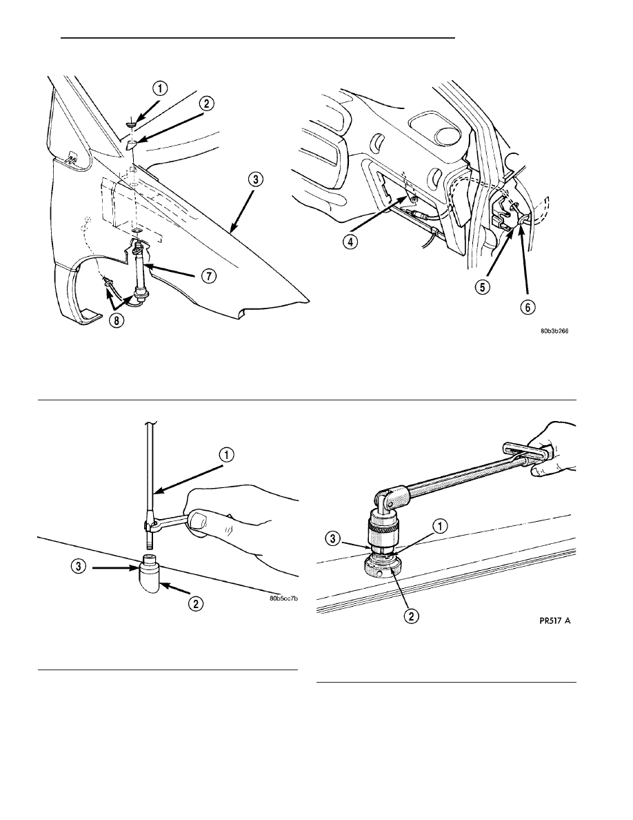
Fig. 3 Antenna Cable

1 - CAP NUT
2 - ADAPTER
3 - FENDER
4 - CABLE TO RADIO (EXTENSION CABLE)

5 - A-PILLAR
6 - RUBBER GROMMET
7 - ANTENNA CABLE AND BODY ASSEMBLY
8 - RUBBER GROMMET

Fig. 4 Antenna Mast

1 - ANTENNA MAST
2 - ADAPTER
3 - CAP NUT

Fig. 5 Antenna Cap Nut

1 - CAP NUT
2 - ANTENNA ADAPTER
3 - TOOL

RS

AUDIO/VIDEO

8A - 9

ANTENNA BODY AND CABLE (Continued)

ANTENNA MODULE - EXPORT

DESCRIPTION

The antenna module is an electromagnetic circuit

component designed to capture and enhance RF
(Radio Frequency) signals in both the AM and FM
broadcast bands. The antenna module is mounted to
the right rear roof rail under the headliner. The mod-
ule is grounded through the mounting bracket and
fastener. The module has a two wire electrical con-
nector that connects to the integral radio antenna,

located on the right rear quarter glass. There is also
an electrical connector for battery voltage and a coax
cable connector.

OPERATION

The antenna module receives both AM and FM

radio signals supplied by the side window integral
radio antenna system and selectively amplifies them.
The amplified signal is then sent through the body
length coax cable to the radio input.

DIAGNOSIS AND TESTING

ANTENNA MODULE - EXPORT

CONDITION

POSSIBLE CAUSES

CORRECTION

NO AM RECEPTION,

WEAK FM RECEPTION

1. Antenna module to antenna
connector open or disconnected.

1. Repair open, reconnect
antenna module connector to
glass mounted antenna.

2. Coax open or disconnected.

2. Repair open, reconnect coax.

3. No battery power at antenna
module.

3. Check fuse. if okay, repair
open in battery voltage circuit.

NO AM OR FM

RECEPTION

1. Coax disconnected at radio.

1. Reconnect coax.

2. Coax shorted to ground.

2. Repair or Replace coax

WEAK OR NO AM/FM

RECEPTION

1. Antenna Module faulty.

1. Replace antenna module

REMOVAL

(1) Disconnect and isolate the battery negative

cable.

(2) Lower

headliner

as

necessary

to

access

antenna module (Fig. 6).

(3) Disconnect antenna coax cable lead and electri-

cal harness connector from antenna module.

(4) Disconnect the antenna module connector from

the quarter glass.

(5) Remove the mounting screw and the antenna

module.

INSTALLATION

(1) Install the antenna module and the mounting

fastener.

(2) Connect the antenna connector to the quarter

glass.

(3) Connect the antenna lead and electrical con-

nector to the antenna module.

(4) Raise and install headliner.
(5) Connect the battery negative cable.

Fig. 6 ANTENNA MODULE

1 - ANTENNA MODULE
2 - ANTENNA MODULE CONNECTOR

8A - 10

AUDIO/VIDEO

RS

ANTENNA - NAVIGATION
RADIO

REMOVAL

(1) Disconnect and isolate the battery negative

cable.

(2) Remove the radio (Refer to 8 - ELECTRICAL/

AUDIO/RADIO - REMOVAL).

(3) Disconnect antenna from radio (Fig. 7). Remove

tape securing antenna to air duct, and remove
antenna (Fig. 8).

INSTALLATION

(1) Secure antenna to air duct.
(2) Connect antenna to radio.
(3) Install radio (Refer to 8 - ELECTRICAL/AU-

DIO/RADIO - INSTALLATION).

(4) Connect battery negative cable.

CD CHANGER

DESCRIPTION

The 6 Disc In-Dash CD Changer (if equipped) is

located in the instrument panel below the radio. The
remote changer does not use a cartridge or magazine
for the CD’s. Up to 6 CD’s can be directly loaded into
this unit.

OPERATION

Due to its compact design, the CD changer can

carry out only one operation at a time. For example,
you can not load a new disc while playing another at
the same time. Each operation happens sequentially.

The radio unit provides control over all features of

the CD changer with the exception of the CD load
and eject functions, which are controlled by buttons
located on the front of the CD changer. All features
you would expect, such as Disc Up/Down, Track
Up/Down, Random and Scan are controlled by the
radio, which also displays all relevant CD changer
information on the radio display.

The CD changer contains a Eject button, six disc

buttons, an indicator LED for each of the six disc
positions as well as an illuminated disc opening. The
individual LED indicates whether a CD is currently
loaded in that particular chamber of the CD changer.
Pressing the individual button for a particular cham-
ber, then the Eject button will eject a disc currently
present in that chamber. If the chamber is currently
empty, actuating the individual button will position
that chamber to receive and load a new disc in that
chamber.

REMOVAL

(1) Disconnect and isolate the battery negative

cable.

(2) Remove screws holding CD changer.
(3) Disconnect the wire connector from the back of

the CD changer.

(4) Remove the CD changer from the vehicle (Fig.

9).

INSTALLATION

(1) Reconnect

the

wire

connector

to

the

CD

changer.

(2) Insert the CD changer into the instrument

panel.

NOTE: Use care when inserting CD changer so that
cable is not pinched or trapped against instrument
panel.

Fig. 7 NAVIGATION ANTENNA

Fig. 8 NAVIGATION ANTENNA MOUNTING

RS

AUDIO/VIDEO

8A - 11

(3) Install screws holding CD changer.
(4) Reconnect the battery negative cable.

DVD PLAYER

DESCRIPTION

The DVD player (if equipped) is located in the

instrument panel below the radio. The DVD player
can hold one DVD at a time. Three RCA jacks on the
front of the unit allow the use of MP3 players, video
game systems or camcorders.

REMOVAL

(1) Disconnect and isolate the battery negative

cable.

(2) Remove screws holding DVD player (Fig. 10).

(3) Disconnect the wire connector from the back of

the DVD player.

(4) Remove the DVD player from the vehicle.

INSTALLATION

(1) Connect the wire harness connector to the DVD

player.

(2) Insert the DVD player into the instrument

panel.

(3) Install mounting screws.
(4) Connect the battery negative cable.

INSTRUMENT PANEL
ANTENNA CABLE

REMOVAL

WARNING: ON VEHICLES EQUIPPED WITH AIR-
BAGS,

REFER

TO

ELECTRICAL,

RESTRAINTS

BEFORE ATTEMPTING ANY STEERING WHEEL,
STEERING

COLUMN,

OR

INSTRUMENT

PANEL

COMPONENT DIAGNOSIS OR SERVICE. FAILURE
TO TAKE THE PROPER PRECAUTIONS COULD
RESULT IN ACCIDENTAL AIRBAG DEPLOYMENT
AND POSSIBLE PERSONAL INJURY.

(1) Disconnect and isolate the battery negative

cable.

(2) Remove glove box (Refer to 23 - BODY/IN-

STRUMENT PANEL/GLOVE BOX - REMOVAL).

(3) Disconnect extension cable end from antenna

cable end.

(4) Disconnect cable hanger clip from HVAC unit.
(5) Remove radio as necessary to gain access to

extension cable (Refer to 8 - ELECTRICAL/AUDIO/
RADIO - REMOVAL).

CAUTION: Pulling the antenna cable straight out of
the radio without pulling on the locking antenna
connector could damage the cable or radio.

(6) Disconnect the antenna cable by pulling the

locking antenna connector away from the radio (Fig.
11).

(7) Remove cable from vehicle.

INSTALLATION

(1) Install extension cable to vehicle.
(2) Connect extension cable to back of radio.
(3) Install radio (Refer to 8 - ELECTRICAL/AU-

DIO/RADIO - INSTALLATION).

(4) Connect cable hanger clip to HVAC unit.
(5) Connect extension cable end to antenna cable

end.

Fig. 9 CD - CHANGER

1 - CD-CHANGER
2 - POWER OUTLET

Fig. 10 DVD PLAYER

1 - DVD PLAYER
2 - POWER OUTLET

8A - 12

AUDIO/VIDEO

RS

CD CHANGER (Continued)


Content   ..  690  691  692  693   ..