Chrysler RG Voyager. Manual - part 662
INSTALLATION
(1) Apply sealant such as Mopar Gasket-In-A-Tube
or equivalent around the wheel cylinder opening in
the brake support plate.
(2) Install wheel cylinder onto brake support.
Install and tighten the wheel cylinder to brake sup-
port plate attaching bolts to 8 N·m (75 in. lbs.)
torque.
(3) Install brake tube into wheel cylinder. Tighten
tube nut to a torque of 17 N·m (145 in. lbs.) torque.
(4) Install the rear brake shoes on the brake sup-
port plate. (Refer to 5 - BRAKES/HYDRAULIC/ME-
CHANICAL/BRAKE
PADS/SHOES
-
INSTALLATION).
(5) Install brake drum.
(6) Install wheel and tire. Install and tighten
wheel lug nuts to 135 N·m (100 ft. lbs.).
(7) Adjust
drum
brake
shoes.
(Refer
to
5
-
BRAKES/HYDRAULIC/MECHANICAL/BRAKE
PADS/SHOES - ADJUSTMENTS)
(8) Remove brake pedal depressor tool.
(9) Bleed the brake system as necessary. (Refer to
5 - BRAKES - BASE - STANDARD PROCEDURE).
(10) Lower vehicle.
PARKING BRAKE
DESCRIPTION
DESCRIPTION
The parking brake system is operated by a foot
operated parking brake lever. The parking brake
lever is mounted on the body of the vehicle to the left
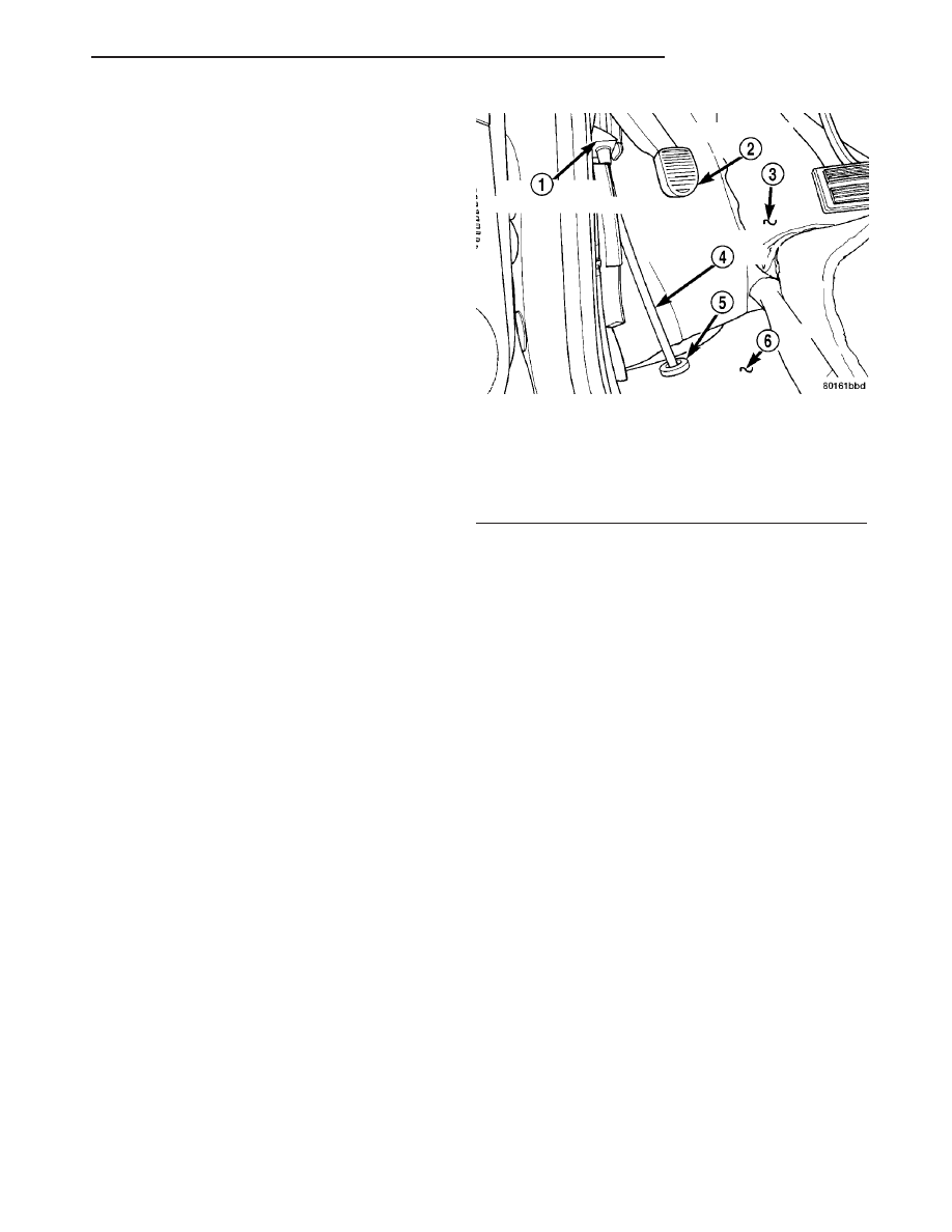
of the brake pedal (Fig. 94). It is a automatic-adjust-
ing type lever.
Vehicles without Fold-in-floor seating have four
flexible steel parking brake cables. They are:
• Front
• Intermediate
• Left rear
• Right rear
Vehicles with Fold-in-floor seating have three flex-
ible steel parking brake cables. They are:
• Front
• Left rear
• Right rear
The front parking brake cable extends from the
parking brake lever. A steel equalizer bracket con-
nects the front parking brake cable to the left rear
and intermediate cables on vehicles without Fold-in-
floor seating. The equalizer bracket connects the
front parking brake cable to the left rear and right
rear cables on vehicles with Fold-in-floor seating. The
intermediate cable is connected to the right rear
cable on vehicles without Fold-in-floor seating. A
standard cable connector is used to accomplish this
connection.
On vehicles equipped with rear drum brakes, the
rear service brakes also act as the vehicle’s parking
brakes.
Vehicles equipped with rear disc brakes use a
small duo-servo brake assembly mounted to the each
rear disc brake caliper adapter as the parking brake.
The inside of the brake rotor (hat section of drum-in-
hat style brake rotor) is used as the parking brake
drum.
DESCRIPTION - EXPORT
The parking brake system on this vehicle features
a hand-operated parking brake lever. The lever is
located between the two front seats and requires a
special front cable.
OPERATION
The automatic-adjusting feature in the foot oper-
ated parking brake lever continuously applies mini-
mal tension to the parking brake cables when the
parking brake lever is in the released position to
keep them in adjustment at all times. Due to this
feature, the parking brake cables require no periodic
adjustment.
When the parking brake lever is applied, the
cables are pulled, thus applying the brake shoes
(rear drum brakes) or parking brake shoes (rear disc
brakes) at each rear wheel.
Fig. 94 Parking Brake Lever (Pedal)
1 - PARK BRAKE PEDAL ASSEMBLY
2 - PARK BRAKE PEDAL
3 - CARPET
4 - FRONT PARK BRAKE CABLE
5 - SEAL
6 - FLOOR PAN
RS
BRAKES - BASE
5 - 61
WHEEL CYLINDERS (Continued)