Chrysler RG Voyager. Manual - part 645
 

  Index      Chrysler     Chrysler RG Voyager - service repair manual 2005 year


Search            


Content   ..  643  644  645  646   ..


Chrysler RG Voyager. Manual - part 645


INSTALLATION

(1) Slide inner CV joint seal boot retaining clamp,

onto the interconnecting shaft. Then, slide the
replacement inner CV joint sealing boot onto the
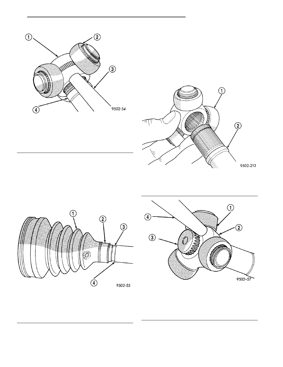
interconnecting shaft. Inner CV joint seal boot
MUST be positioned on interconnecting shaft
so the raised bead on the inside of the small
diameter end of the seal boot is in mating
groove on interconnecting shaft (Fig. 15).

(2) Install spider assembly onto interconnecting

shaft (Fig. 16). Spider assembly must be installed on
interconnecting shaft far enough to fully install spi-
der retaining snap-ring. If the spider assembly will
not fully install on interconnecting shaft by hand, it
can be installed by tapping the spider body with a
brass drift (Fig. 17). Do not hit the outer tripod
bearings in an attempt to install spider assem-
bly on interconnecting shaft.

Fig. 14 Spider Assembly Removal from

Interconnecting Shaft

1 - SPIDER ASSEMBLY
2 - DO NOT HIT SPIDER ASSEMBLY BEARINGS WHEN
REMOVING SPIDER ASSEMBLY
3 - BRASS DRIFT
4 - INTERCONNECTING SHAFT

Fig. 15 Sealing Boot Installation on Interconnecting

Shaft

1 - SEALING BOOT
2 - RAISED BEAD IN THIS AREA OF SEALING BOOT
3 - GROOVE
4 - INTERCONNECTING SHAFT

Fig. 16 Spider Assembly Installation on

Interconnecting Shaft

1 - SPIDER ASSEMBLY
2 - INTERCONNECTING SHAFT

Fig. 17 Installing Spider Assembly on

Interconnecting Shaft

1 - DO NOT HIT BEARINGS WHEN INSTALLING THE SPIDER
ASSEMBLY
2 - SPIDER ASSEMBLY
3 - INTERCONNECTING SHAFT
4 - BRASS DRIFT

RS

HALF SHAFT - FRONT

3 - 7

CV BOOT - INNER (Continued)

(3) Install the spider assembly to interconnecting

shaft retaining snap-ring into groove on end of inter-
connecting shaft (Fig. 18). Be sure the snap-ring is
fully seated into groove on interconnecting shaft.

(4) Distribute 1/2 the amount of grease provided in

the seal boot service package (DO NOT USE ANY
OTHER TYPE OF GREASE) into tripod housing. Put
the remaining amount into the sealing boot.

(5) Align tripod housing with spider assembly and

then slide tripod housing over spider assembly and
interconnecting shaft (Fig. 19).

(6) Install inner CV joint seal boot to interconnect-

ing shaft clamp evenly on sealing boot.

(7) Place crimping tool C-4975-A over bridge of

clamp (Fig. 20).

(8) Tighten nut on crimping tool C-4975-A until

jaws on tool are closed completely together, face to
face (Fig. 21).

CAUTION: Seal boot must not be dimpled, stretched
or out of shape in any way. If seal boot is NOT
shaped correctly, equalize pressure in seal and
shape it by hand.

Fig. 18 Spider Assembly Retaining Snap-Ring

Installed

1 - INTERCONNECTING SHAFT
2 - SPIDER ASSEMBLY
3 - RETAINING SNAP-RING

Fig. 19 Installing Tripod Housing on Spider

Assembly

1 - TRIPOD JOINT HOUSING
2 - SPIDER ASSEMBLY
3 - SEALING BOOT

Fig. 20 Crimping Tool Installed on Sealing Boot

Clamp - Typical

1 - SPECIAL TOOL C-4975-A
2 - INTERCONNECTING SHAFT
3 - CLAMP
4 - SEALING BOOT

Fig. 21 Sealing Boot Retaining Clamp Installed -

Typical

1 - CLAMP
2 - JAWS OF SPECIAL TOOL C-4975-A MUST BE CLOSED
COMPLETELY TOGETHER HERE
3 - INTERCONNECTING SHAFT
4 - SEALING BOOT

3 - 8

HALF SHAFT - FRONT

RS

CV BOOT - INNER (Continued)

(9) Position sealing boot into the tripod housing

retaining groove. Install seal boot retaining clamp
evenly on sealing boot.

(10) Position trilobal boot to interface with the tri-

pod housing. The lobes of the boot must be properly
aligned with the recess’s of the tripod housing.

CAUTION: The following positioning procedure deter-
mines the correct air pressure inside the inner CV
joint assembly prior to clamping the sealing boot to
inner CV joint housing. If this procedure is not done
prior to clamping sealing boot to CV joint housing
sealing boot durability can be adversely affected.

CAUTION: When venting the inner CV joint assembly,
use care so that the inner CV sealing boot does not
get punctured, or in any other way damaged. If sealing
boot is punctured, or damaged in any way while being
vented, the sealing boot can not be used.

(11) Insert a trim stick between the CV joint hous-

ing and the sealing boot insert to vent inner CV joint
assembly (Fig. 22). When inserting trim stick
between

tripod

housing

and

sealing

boot

ensure trim stick is held flat and firmly against
the tripod housing. If this is not done damage
to the sealing boot can occur.

(12) With trim stick inserted between sealing boot

insert and the CV joint housing, position the intercon-
necting shaft so it is at the center of its travel in the
tripod joint housing. Remove the trim stick from
between the sealing boot insert and the CV joint hous-
ing. This procedure will equalize the air pressure

in the CV joint, preventing premature sealing
boot failure.

(13) Clamp CV joint sealing boot to CV joint, using

required procedure for type of boot clamp application.

CRIMP TYPE BOOT CLAMP

If seal boot uses crimp type boot clamp, use the fol-

lowing procedure to install the retaining clamp.

(1) Place crimping tool C-4975-A over bridge of

clamp (Fig. 23).

(2) Tighten nut on crimping tool C-4975-A until

jaws on tool are closed completely together, face to
face (Fig. 24).

Fig. 22 Trim Stick Inserted for Venting CV Joint

1 - INNER CV JOINT SEALING BOOT
2 - SEALING BOOT CLAMP
3 - INNER CV JOINT HOUSING
4 - TRIM STICK

Fig. 23 Crimping Tool Installed on Sealing Boot Clamp

1 - CLAMP
2 - TRIPOD JOINT HOUSING
3 - SPECIAL TOOL C-4975-A
4 - SEALING BOOT

Fig. 24 Sealing Boot Retaining Clamp Installed

1 - CLAMP
2 - TRIPOD HOUSING
3 - SPECIAL TOOL C-4975-A
4 - JAWS OF SPECIAL TOOL C-4975-A MUST BE CLOSED
COMPLETELY TOGETHER HERE
5 - SEALING BOOT

RS

HALF SHAFT - FRONT

3 - 9

CV BOOT - INNER (Continued)

LATCHING TYPE BOOT CLAMP

If seal boot uses low profile latching type boot

clamp, use the following procedure to install the
retaining clamp.

(1) Place prongs of clamp locking tool in the holes

of the clamp (Fig. 25).

(2) Squeeze tool together until top band of clamp is

latched behind the two tabs on lower band of clamp
(Fig. 26).

(14) Install the half shaft back into the vehicle.

(Refer to 3 - DIFFERENTIAL & DRIVELINE/HALF
SHAFT - INSTALLATION)

CV BOOT - OUTER

REMOVAL

(1) Remove

halfshaft

assembly

requiring

boot

replacement from vehicle. (Refer to 3 - DIFFEREN-
TIAL & DRIVELINE/HALF SHAFT - REMOVAL)

(2) Remove large boot clamp retaining C/V joint

sealing boot to C/V joint housing (Fig. 27) and dis-
card. Remove small clamp that retains outer C/V
joint sealing boot to interconnecting shaft and dis-
card. Remove sealing boot from outer C/V joint hous-
ing and slide it down interconnecting shaft.

(3) Wipe away grease to expose outer C/V joint and

interconnecting shaft.

(4) Remove outer C/V joint from interconnecting

shaft using the following procedure: Support inter-
connecting shaft in a vise equipped with protective
caps on jaws of vise to prevent damage to intercon-
necting shaft. Then, using a soft–faced hammer,
sharply hit the end of the C/V joint housing to dis-
lodge housing from internal circlip on interconnecting
shaft (Fig. 28). Then slide outer C/V joint off end of
interconnecting shaft, joint may have to be tapped off
shaft using a soft–faced hammer.

(5) Remove large circlip (Fig. 29) from the inter-

connecting shaft before attempting to remove outer
C/V joint sealing boot.

(6) Slide sealing boot off interconnecting shaft.
(7) Thoroughly clean and inspect outer C/V joint

assembly and interconnecting joint for any signs of
excessive wear. If any parts show signs of exces-
sive wear, the halfshaft assembly will require
replacement. Component parts of these half-
shaft assemblies are not serviceable.

Fig. 25 Clamping Tool Installed on Sealing Boot

Clamp

1 - CLAMP
2 - TOOL YA3050, OR EQUIVALENT
3 - SEALING BOOT

Fig. 26 Sealing Boot Clamp Correctly Installed

1 - INNER TRIPOD JOINT HOUSING
2 - TOP BAND OF CLAMP MUST BE RETAINED BY TABS AS
SHOWN HERE TO CORRECTLY LATCH BOOT CLAMP
3 - SEALING BOOT

Fig. 27 Outer C/V Joint Seal Boot Clamps

1 - SMALL CLAMP
2 - SEALING BOOT
3 - OUTER C/V JOINT HOUSING
4 - LARGE CLAMP
5 - INTERCONNECTING SHAFT

3 - 10

HALF SHAFT - FRONT

RS

CV BOOT - INNER (Continued)


Content   ..  643  644  645  646   ..