Chrysler RG Voyager. Manual - part 559
TEST
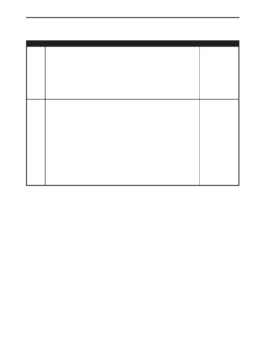
ACTION
APPLICABILITY
16
Turn the ignition off.
Disconnect the Ignition Coil harness connector.
Using a 12-volt test light connected to 12-volts, probe the Ignition Coil Control
circuit.
Crank the engine for 5 second while observing the test light.
Does the test light blink/flicker?
All
Yes
→ Replace the Ignition Coil.
Perform POWERTRAIN VERIFICATION TEST VER - 5.
No
→ Go To 17
17
Turn the ignition off.
Disconnect the Ignition Coil harness connector.
Disconnect the PCM harness connector.
CAUTION: DO NOT PROBE THE PCM HARNESS CONNECTORS. PROBING
THE PCM HARNESS CONNECTORS WILL DAMAGE THE PCM TERMI-
NALS RESULTING IN POOR TERMINAL TO PIN CONNECTION. INSTALL
MILLER SPECIAL TOOL #8815 TO PERFORM DIAGNOSIS.
Check the Coil Control circuit.
Was a problem found with the Coil Control circuit?
All
Yes
→ Repair the Coil Control circuit.
Perform POWERTRAIN VERIFICATION TEST VER - 5.
No
→ NOTE: Before continuing, check the PCM harness connector
terminals for corrosion, damage, or terminal push out. Repair as
necessary. Replace and program the Powertrain Control Module
in accordance with the Service Information.
Perform POWERTRAIN VERIFICATION TEST VER - 5.
118
DRIVEABILITY - NGC
P0300-MULTIPLE CYLINDER MISFIRE —
Continued