Chrysler RG Voyager. Manual - part 1084


  Index      Chrysler     Chrysler RG Voyager - service repair manual 2005 year


Search            


Content   ..  1082  1083  1084  1085   ..


Chrysler RG Voyager. Manual - part 1084


INSTALLATION

(1) Fish gear shift cable dash panel opening into

engine compartment and secure grommet (Fig. 214).

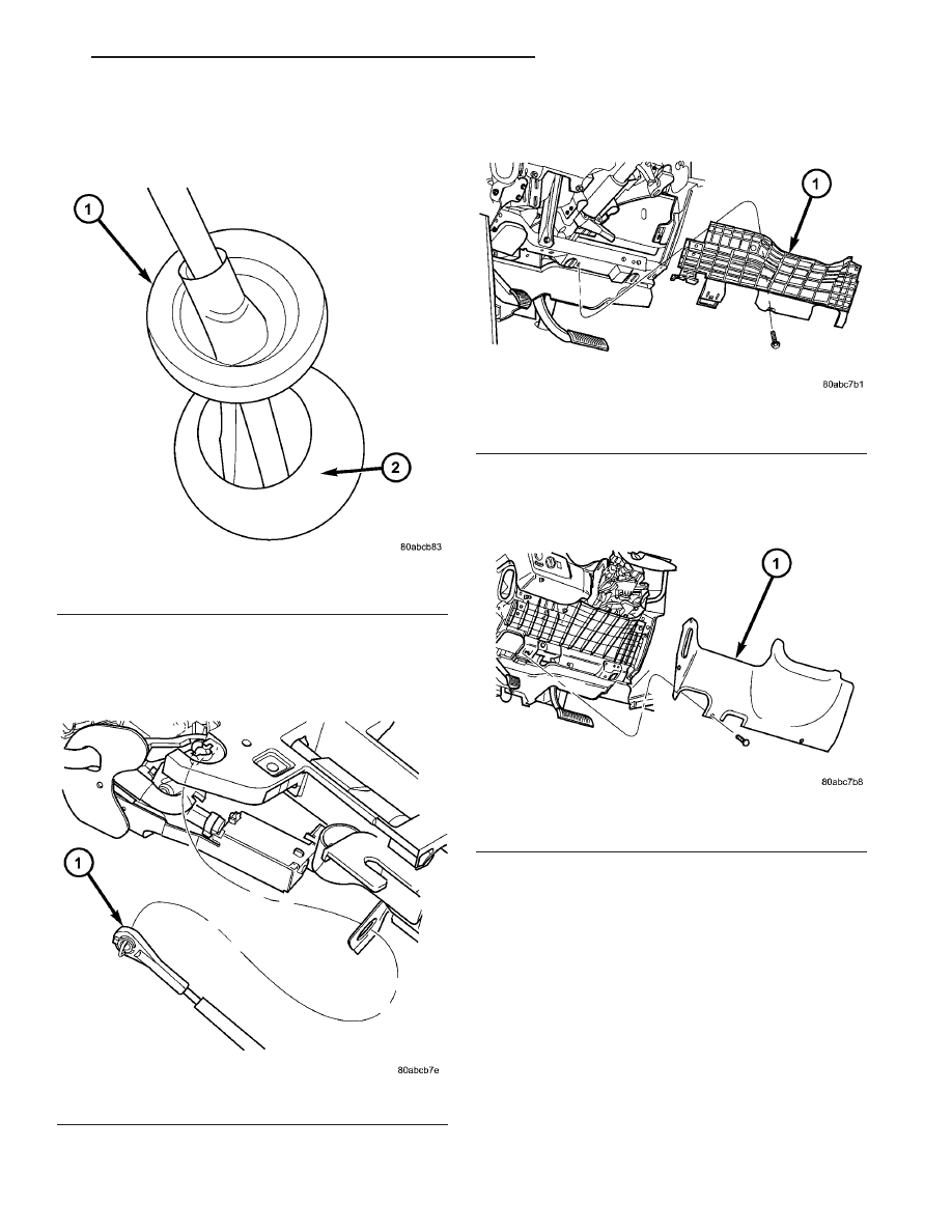
(2) Install gear shift cable through column bracket

(Fig. 215) until audible “click” is heard.

(3) Connect gear shift cable to gear shift lever (Fig.

215).

(4) Install knee bolster (Fig. 216).

(5) Install instrument panel lower silencer (Fig.

217).

(6) Install gear shift cable to transaxle upper

mount bracket (Fig. 218). An audible “click” should
be heard.

(7) Connect gear shift cable end to transaxle man-

ual valve lever (Fig. 218).

Fig. 214 Gearshift Cable/Grommet at Dash Panel

1 - CABLE GROMMET
2 - DASH PANEL

Fig. 215 Gearshift Cable at Column

1 - GEAR SHIFT CABLE

Fig. 216 Knee Bolster

1 - KNEE BOLSTER

Fig. 217 Instrument Panel Lower Silencer

1 - INSTRUMENT PANEL LOWER SILENCER

RS

41TE AUTOMATIC TRANSAXLE

21 - 357

GEAR SHIFT CABLE (Continued)

(8) Adjust gearshift cable. (Refer to 21 - TRANS-

MISSION/TRANSAXLE/AUTOMATIC - 41TE/GEAR
SHIFT CABLE - ADJUSTMENTS)

(9) Install speed control servo into position.
(10) Install battery.
(11) Install battery shield.
(12) Connect battery cables.

ADJUSTMENTS

GEARSHIFT CABLE ADJUSTMENT

VERIFICATION

(1) Place gearshift lever in gated park (P).
(2) Attempt to move vehicle by rocking back and

forth on level ground. If vehicle does not move,
attempt to start engine. If engine starts, the park
position is correct.

(3) Set parking brake.
(4) Turn key to on/run and depress brake pedal.

Place gearshift lever in neutral (N).

(5) Attempt to start engine. If engine starts in

both neutral (N) or park (P), gearshift cable is
adjusted properly. No adjustment is required.

(6) If engine does not start in either park (P) or

neutral (N), perform adjustment procedure.

ADJUSTMENT

(1) Park the vehicle on level ground and set the

parking brake.

(2) Place the gearshift lever in gated park (P) and

remove ignition key.

(3) Loosen the cable adjustment screw at the

transaxle manual valve lever (Fig. 219).

(4) Pull the gearshift lever fully forward to the

park detent position.

(5) Release the park brake, then rock the vehicle

to assure it is in park. Reset the park brake.

(6) Tighten the cable adjustment screw to 8 N·m

(70 in. lbs.). Gearshift cable should now be properly
adjusted.

(7) Verify adjustment by using the verification pro-

cedure.

HOLDING CLUTCHES

DESCRIPTION

Two hydraulically applied multi-disc clutches are

used to hold planetary geartrain components station-
ary while the input clutches drive others. The 2/4
and Low/Reverse clutches are considered holding
clutches and are contained at the rear of the trans-
axle case. (Fig. 220).

Fig. 218 Gearshift Cable at Transaxle

1 - MANUAL VALVE LEVER
2 - GEAR SHIFT CABLE
3 - UPPER MOUNT BRACKET

Fig. 219 Gearshift Cable Adjustment

1 - GEARSHIFT CABLE ADJUSTMENT SCREW
2 - GEARSHIFT CABLE

21 - 358

41TE AUTOMATIC TRANSAXLE

RS

GEAR SHIFT CABLE (Continued)

OPERATION

NOTE: Refer to the “Elements In Use” chart in Diag-
nosis and Testing for a collective view of which
clutch elements are applied at each position of the
selector lever.

2/4 CLUTCH

The 2/4 clutch is hydraulically applied in second

and fourth gears by pressurized fluid against the 2/4
clutch piston. When the 2/4 clutch is applied, the
front sun gear assembly is held or grounded to the
transaxle case.

LOW/REVERSE CLUTCH

The Low/Reverse clutch is hydraulically applied in

park, reverse, neutral, and first gears by pressurized
fluid against the Low/Reverse clutch piston. When
the Low/Reverse clutch is applied, the front planet
carrier/rear annulus assembly is held or grounded to
the transaxle case.

INPUT CLUTCH ASSEMBLY

DISASSEMBLY

(1) Mount input clutch assembly to Input Clutch

Pressure Fixture (Tool 8391).

(2) Tap down reverse clutch reaction plate to

release pressure from snap ring (Fig. 221).

(3) Remove reverse clutch snap ring (Fig. 222).

(4) Pry up and remove reverse clutch reaction

plate (Fig. 223).

Fig. 220 2/4 and Low/Reverse Clutches

1 - FRONT PLANET CARRIER/REAR ANNULUS
2 - 2/4 CLUTCH
3 - L/R CLUTCH
4 - REAR PLANET CARRIER/FRONT ANNULUS
5 - REAR SUN GEAR
6 - FRONT SUN GEAR ASSEMBLY

Fig. 221 Tapping Reaction Plate

1 - #4 THRUST PLATE (SELECT)
2 - TAP DOWN REVERSE CLUTCH REACTION PLATE TO
REMOVE OR INSTALL SNAP RING
3 - INPUT SHAFT CLUTCHES RETAINER ASSEMBLY
4 - REVERSE CLUTCH REACTION PLATE

Fig. 222 Reverse Clutch Snap Ring

1 - REACTION PLATE
2 - SCREWDRIVER
3 - REVERSE CLUTCH SNAP RING (SELECT)

RS

41TE AUTOMATIC TRANSAXLE

21 - 359

HOLDING CLUTCHES (Continued)

(5) Remove reverse clutch pack (Fig. 224). Tag

components for assembly identification.

(6) Remove the OD/Reverse pressure plate snap

ring (Fig. 225).

(7) Remove OD/Reverse pressure plate (Fig. 225).
(8) Remove OD/Reverse pressure plate wave snap

ring (Fig. 225).

(9) Remove OD clutch pack (Fig. 225). Tag com-

ponents for assembly identification.

Fig. 223 Pry Reverse Clutch Reaction Plate

1 - REVERSE CLUTCH REACTION PLATE
2 - SCREWDRIVER
3 - SCREWDRIVER

Fig. 224 Reverse Clutch Assembly

1 - SNAP RING
2 - REACTION PLATE
3 - CLUTCH DISC (2)

4 - CLUTCH PLATE (1)
5 - INPUT CLUTCH ASSEMBLY

21 - 360

41TE AUTOMATIC TRANSAXLE

RS

INPUT CLUTCH ASSEMBLY (Continued)


Content   ..  1082  1083  1084  1085   ..