Chrysler RG Voyager. Manual - part 1003


  Index      Chrysler     Chrysler RG Voyager - service repair manual 2005 year


Search            


Content   ..  1001  1002  1003  1004   ..


Chrysler RG Voyager. Manual - part 1003


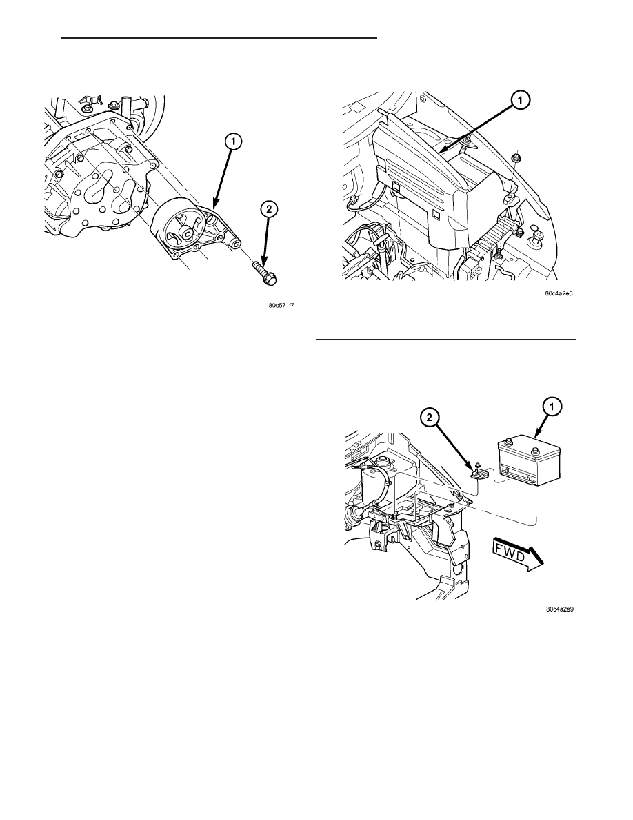
(18) Remove four (4) upper mount-to-transaxle

bolts and remove mount (Fig. 14).

(19) Obtain helper and transmission jack. Secure

transaxle to transmission jack and remove transaxle-
to-engine bolts.

(20) Remove transaxle from engine.
(21) Inspect

modular

clutch

assembly,

clutch

release components, and engine drive plate.

REMOVAL - 2.5L TD

(1) Raise hood.
(2) Disconnect both battery cables.

(3) Remove battery thermal shield (Fig. 15).
(4) Remove battery hold down bolt, clamp, and

battery (Fig. 16).

Fig. 14 Transaxle Upper Mount

1 - MOUNT
2 - BOLT (4)

Fig. 15 Battery Thermal Shield

1 - BATTERY THERMAL SHIELD

Fig. 16 Battery and Hold-Down Clamp

1 - BATTERY
2 - HOLD-DOWN CLAMP

RS

T850 MANUAL TRANSAXLE

21 - 33

T850 MANUAL TRANSAXLE (Continued)

(5) Remove battery tray (Fig. 17). Disconnect bat-

tery temperature sensor.

(6) Remove coolant recovery bottle from bracket.
(7) Remove

coolant

recovery

bottle

mounting

bracket (Fig. 18).

(8) Disconnect gearshift cables from shift levers/

cover assembly (Fig. 19).

(9) Remove gearshift cable retaining clips from

mounting bracket (Fig. 19). Remove cables and
secure out of way.

(10) Remove three (3) right engine mount bracket-

to-transaxle bolts (Fig. 20).

Fig. 17 Battery Tray

1 - BATTERY TRAY

Fig. 18 Coolant Recovery Bottle Bracket

1 - COOLANT RECOVERY BOTTLE BRACKET
2 - NUT
3 - MOUNT BRACKET

Fig. 19 Gearshift Cables at Transaxle

1 - SELECTOR CABLE
2 - CABLE RETAINER
3 - CABLE RETAINER
4 - CROSSOVER CABLE
5 - MOUNT BRACKET

Fig. 20 Transaxle Right Mount and Bracket

1 - MOUNT BRACKET
2 - BOLT (3)
3 - MOUNT
4 - BOLT (1)

21 - 34

T850 MANUAL TRANSAXLE

RS

T850 MANUAL TRANSAXLE (Continued)

(11) Raise vehicle on hoist.
(12) Remove front wheel/tires and halfshafts.
(13) Remove underbody splash shield.
(14) Drain transaxle fluid into suitable container.
(15) Remove front harness retainer and secure

harness out of way.

(16)

Using Tool 6638A, disconnect clutch hydrau-

lic circuit quick connect (located on slave cylinder
tube). Remove clutch slave cylinder by depressing
towards case and rotating counter-clockwise 60°,
while lifting anti-rotation tab out of case slot with
screwdriver (Fig. 21).

(17) Remove engine left mount bracket (Fig. 22).

(18) Remove starter motor (Fig. 23).
(19) Disconnect back-up lamp switch connector.
(20) Position screw jack and wood block to engine

oil pan.

(21) Remove transmission upper mount through-

bolt from left frame rail.

(22) Lower engine/transaxle assembly on screw

jack.

Fig. 21 Slave Cylinder Removal/Installation

1 - MOUNTING HOLE
2 - SLAVE CYLINDER
3 - ACCESS HOLE
4 - NYLON ANTI-ROTATION TAB
5 - QUICK CONNECT

Fig. 22 Left Mount Bracket Removal/Installation

1 - BOLT (2)
2 - MOUNT BRACKET
3 - BOLT (2)

Fig. 23 Starter Motor Removal/Installation

1 - STARTER MOTOR
2 - BOLT (3)

RS

T850 MANUAL TRANSAXLE

21 - 35

T850 MANUAL TRANSAXLE (Continued)

(23) Remove four (4) upper mount-to-transaxle

bolts and remove mount (Fig. 24).

(24) Obtain helper and transmission jack. Secure

transaxle to transmission jack and remove transaxle-
to-engine bolts.

(25) Remove transaxle from engine (Fig. 25).
(26) Inspect clutch, clutch release components, and

flywheel.

DISASSEMBLY

(1) Remove clutch release lever and bearing (Fig.

26). Inspect release lever pivot balls and replace if
necessary (Fig. 27). Use slide hammer C-3752 and
remover/installer 6891 (Fig. 28) if pivot ball replace-
ment is necessary.

Fig. 25 Transaxle Removal/Installation

1 - TRANSAXLE

2 - BOLT

Fig. 24 Transaxle Upper Mount

1 - MOUNT
2 - BOLT (4)

21 - 36

T850 MANUAL TRANSAXLE

RS

T850 MANUAL TRANSAXLE (Continued)


Content   ..  1001  1002  1003  1004   ..