Chrysler PT Cruiser. Manual - part 971
 

  Index      Chrysler     Chrysler PT Cruiser - service repair manual 2005 year


Search            


Content   ..  969  970  971  972   ..


Chrysler PT Cruiser. Manual - part 971


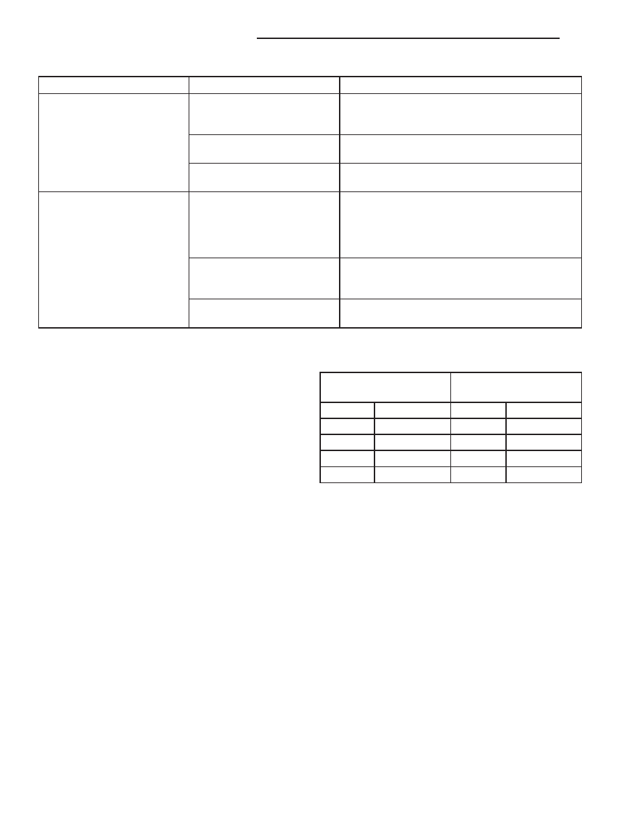
Condition

Possible Causes

Correction

The low side pressure is too
high, and the high side
pressure is too low.

1. Accessory drive belt
slipping.

1. Inspect the accessory drive belt condition and
tension. Tighten or replace the accessory drive
belt, if required. Refer to Group 7.

2. Faulty A/C variable orifice
tube.

2. See A/C Variable Orifice Tube in this group.
Replace if required.

3. Faulty A/C compressor.

3. See A/C Compressor in this group. Replace
the compressor, if required.

The low side pressure is too
low, and the high side
pressure is too high.

1. Restricted refrigerant flow
through the refrigerant lines.

1. See Liquid Line, Suction Line and Discharge
Line in this group. Inspect the refrigerant lines for
kinks, tight bends or improper routing. Correct
the routing or replace the refrigerant line, if
required.

2. Restricted refrigerant flow
through the A/C variable
orifice tube.

2. See A/C Variable Orifice Tube in this group.
Replace if required.

3. Restricted refrigerant flow
through the A/C condenser.

3. See A/C Condenser in this group. Replace the
restricted condenser, if required.

HEATER PERFORMANCE

WARNING: Review safety precautions and warnings
in this group before performing this procedure
(Refer to 24 - HEATING & AIR CONDITIONING/
PLUMBING - WARNINGS) and (Refer to 24 - HEAT-
ING & AIR CONDITIONING/PLUMBING - CAUTIONS).
Failure to follow the warnings and cautions could
result in possible personal injury or death.

Check the coolant level, drive belt tension, radiator

air flow and fan operation. Start engine and allow to
warm up to normal operating temperature.

WARNING: Do not remove radiator cap when engine
is hot, personal injury can result.

If vehicle has been run recently, wait 15 minutes

before removing the radiator cap. Place a rag over
the cap and turn it to the first safety stop. Allow
pressure to escape through the overflow tube. When
the system pressure stabilizes, remove the cap com-
pletely.

MAXIMUM HEATER OUTPUT: TEST AND ACTION

Engine coolant is provided to the heater system by

two heater hoses. With the engine idling at normal
operating temperature, set the temperature control
to maximum heat, the mode control to the floor posi-
tion, and the blower in the highest speed position.
Using a test thermometer, check the temperature of
the air being discharged from the floor outlets. Com-
pare the test thermometer reading to the Heater
Temperature Reference chart.

HEATER TEMPERATURE REFERENCE

Ambient Temperature

Minimum Floor Outlet

Temperature

Celsius

Fahrenheit

Celsius

Fahrenheit

15.5°

60°

62.2°

144°

21.1°

70°

63.8°

147°

26.6°

80°

65.5°

150°

32.2°

90°

67.2°

153°

If the floor outlet air temperature is insufficient,

refer to 7 - COOLING - DIAGNOSIS AND TESTING.
Both heater hoses should be HOT to the touch (cool-
ant return hose should be slightly cooler than the
supply hose). If coolant return hose is much cooler
than the supply hose, locate and repair engine cool-
ant flow obstruction in heater system.

OBSTRUCTED COOLANT FLOW Possible locations or causes
of obstructed coolant flow are as follows:

• Pinched or kinked heater hoses.

• Improper heater hose routing.

• Plugged heater hoses or supply and return ports

at the cooling system connections.

• Plugged heater core.

• Air locked heater core.
If proper coolant flow through the cooling system is

verified, and heater outlet air temperature is insuffi-
cient, a mechanical problem may exist.

MECHANICAL PROBLEMS

Possible causes of insufficient heat due to mechan-

ical problems are as follows:

• Faulty engine thermostat.

24 - 6

HEATING & AIR CONDITIONING

PT

HEATING & AIR CONDITIONING (Continued)

• Faulty temperature control cable.

• Obstructed fresh air intake.

• Obstructed heater system outlets.

• Faulty blend-air door.

TEMPERATURE CONTROL

If the heater outlet air temperature cannot be

adjusted with the temperature control on the A/C-

heater control panel, the following could require ser-
vice:

• Faulty A/C-heater control.

• Faulty temperature control cable.

• Faulty related wiring harness or connectors.

• Faulty blend-air door.

SPECIFICATIONS

HEATING-A/C SYSTEM

A/C SYSTEM

Item

Description

Notes

A/C Compressor

Nippondenso 10S17 - Auto Trans
Nippondenso 10S15 - Man Trans

ND-8 PAG oil

Freeze-up Control

A/C low pressure switch

Input to PCM, accumulator
mounted, cycles clutch off below
152 kPa (22 psi), cycles back on
above 234 -262 kPa (34 - 38 psi)

Low psi Control

A/C low pressure switch

Input to PCM, accumulator
mounted, cycles clutch off below
152 kPa (22 psi), cycles back on
above 234 -262 kPa (34 - 38 psi)

High psi Control

A/C High pressure switch

Input to PCM, A/C Compressor
mounted - opens at discharge
pressure above 3100 - 3375 kPa
(450 - 490 psi) - resets at 1860 -
2275 kPa (270 - 330 psi)

Refrigerant Charge Capacity

Refer to the A/C Underhood
Specification Label located in the
engine compartment.

R-134a refrigerant

A/C Clutch Coil Draw

3.3 amps @ 12V± 0.5V @ 21° C
(70° F)

3.6 ohms when measured across
coil lead connector

A/C Clutch Air Gap

0.35 - 0.60 mm (0.014 - 0.024 in.)

FASTENER TORQUE

Description

N·m

Ft. Lbs.

In. Lbs.

All Screws NOT Listed
Below

2

17

A/C Compressor Shaft
Bolt

17.5

155

A/C Compressor Mounting
Bolts

28

21

Accumulator Bracket Bolt

10

89

Accumulator Tubes to
Evaporator Tapping Block
Bolts

11

97

PT

HEATING & AIR CONDITIONING

24 - 7

HEATING & AIR CONDITIONING (Continued)

Description

N·m

Ft. Lbs.

In. Lbs.

Discharge Line to
Compressor Bolt

12

106

Discharge Line to
Condenser Nut

5

44

HVAC Housing Outboard
Bolt

4.5

40

HVAC Housing Stud Nuts

4.5

40

Liquid Line to Accumulator
Tube Nut

5

44

Liquid Line to Condenser
Nut

5

44

Suction Line to
Accumulator Tube Nut

5

44

Suction Line to
Compressor Bolt

12

106

Windshield Washer
Reservoir Bolts

8

70

24 - 8

HEATING & AIR CONDITIONING

PT

HEATING & AIR CONDITIONING (Continued)

CONTROLS

TABLE OF CONTENTS

page

page

A/C COMPRESSOR CLUTCH COIL

DESCRIPTION

. . . . . . . . . . . . . . . . . . . . . . . . . . 9

OPERATION

. . . . . . . . . . . . . . . . . . . . . . . . . . . . 9

DIAGNOSIS AND TESTING

A/C COMPRESSOR CLUTCH COIL

. . . . . . . . 10

STANDARD PROCEDURE

A/C CLUTCH INSPECTION

. . . . . . . . . . . . . . 11

A/C CLUTCH BREAK-IN

. . . . . . . . . . . . . . . . 11

REMOVAL

. . . . . . . . . . . . . . . . . . . . . . . . . . . . . 11

INSTALLATION

. . . . . . . . . . . . . . . . . . . . . . . . . 12

A/C CLUTCH RELAY

DESCRIPTION

. . . . . . . . . . . . . . . . . . . . . . . . . 13

OPERATION

. . . . . . . . . . . . . . . . . . . . . . . . . . . 14

REMOVAL

. . . . . . . . . . . . . . . . . . . . . . . . . . . . . 14

INSTALLATION

. . . . . . . . . . . . . . . . . . . . . . . . . 14

A/C HEATER CONTROL

DESCRIPTION

. . . . . . . . . . . . . . . . . . . . . . . . . 15

DIAGNOSIS AND TESTING

VACUUM CONTROL SYSTEM

. . . . . . . . . . . . 15

REMOVAL

. . . . . . . . . . . . . . . . . . . . . . . . . . . . . 17

INSTALLATION

. . . . . . . . . . . . . . . . . . . . . . . . . 18

A/C HIGH PRESSURE SWITCH

DESCRIPTION

. . . . . . . . . . . . . . . . . . . . . . . . . 18

OPERATION

. . . . . . . . . . . . . . . . . . . . . . . . . . . 18

DIAGNOSIS AND TESTING

A/C HIGH PRESSURE SWITCH

. . . . . . . . . . . 19

REMOVAL

. . . . . . . . . . . . . . . . . . . . . . . . . . . . . 19

INSTALLATION

. . . . . . . . . . . . . . . . . . . . . . . . . 19

A/C LOW PRESSURE SWITCH

DESCRIPTION

. . . . . . . . . . . . . . . . . . . . . . . . . 20

OPERATION

. . . . . . . . . . . . . . . . . . . . . . . . . . . 20

DIAGNOSIS AND TESTING

A/C LOW PRESSURE SWITCH

. . . . . . . . . . . 20

REMOVAL

. . . . . . . . . . . . . . . . . . . . . . . . . . . . . 20

INSTALLATION

. . . . . . . . . . . . . . . . . . . . . . . . . 20

BLOWER MOTOR RESISTOR

DESCRIPTION

. . . . . . . . . . . . . . . . . . . . . . . . . 21

OPERATION

. . . . . . . . . . . . . . . . . . . . . . . . . . . 21

DIAGNOSIS AND TESTING

BLOWER MOTOR RESISTOR

. . . . . . . . . . . . 21

REMOVAL

. . . . . . . . . . . . . . . . . . . . . . . . . . . . . 22

INSTALLATION

. . . . . . . . . . . . . . . . . . . . . . . . . 22

MODE DOOR CABLE

REMOVAL

. . . . . . . . . . . . . . . . . . . . . . . . . . . . . 22

INSTALLATION

. . . . . . . . . . . . . . . . . . . . . . . . . 23

RECIRCULATION DOOR ACTUATOR

DESCRIPTION

. . . . . . . . . . . . . . . . . . . . . . . . . 23

OPERATION

. . . . . . . . . . . . . . . . . . . . . . . . . . . 23

REMOVAL

. . . . . . . . . . . . . . . . . . . . . . . . . . . . . 23

INSTALLATION

. . . . . . . . . . . . . . . . . . . . . . . . . 24

TEMPERATURE CONTROL CABLE

REMOVAL

. . . . . . . . . . . . . . . . . . . . . . . . . . . . . 24

INSTALLATION

. . . . . . . . . . . . . . . . . . . . . . . . . 25

VACUUM CHECK VALVE

DESCRIPTION

. . . . . . . . . . . . . . . . . . . . . . . . . 25

OPERATION

. . . . . . . . . . . . . . . . . . . . . . . . . . . 25

REMOVAL

. . . . . . . . . . . . . . . . . . . . . . . . . . . . . 25

INSTALLATION

. . . . . . . . . . . . . . . . . . . . . . . . . 25

A/C COMPRESSOR CLUTCH
COIL

DESCRIPTION

The A/C compressor clutch assembly consists of a

stationary electromagnetic A/C clutch field coil, a pul-
ley bearing and pulley assembly, and a clutch plate
(Fig. 1). These components provide the means to
engage and disengage the A/C compressor from the
engine accessory drive belt.

The A/C clutch field coil and the pulley bearing

and pulley assembly are both retained on the nose of
the A/C compressor with snap rings. The clutch plate
is splined to the compressor shaft and secured with a
bolt.

OPERATION

When the clutch coil is energized, it magnetically

draws the clutch into contact with the pulley and
drives the compressor shaft. When the coil is not
energized, the pulley freewheels on the clutch hub
bearing, which is part of the pulley. The compressor
clutch and coil are the only serviced parts on the
compressor.

A/C compressor clutch engagement is controlled by

the following components:

• A/C-heater mode control switch

• A/C low pressure switch

• A/C high pressure switch

• A/C compressor clutch relay

• Powertrain Control Module (PCM)

PT

CONTROLS

24 - 9


Content   ..  969  970  971  972   ..