Chrysler PT Cruiser. Manual - part 735


  Index      Chrysler     Chrysler PT Cruiser - service repair manual 2005 year


Search            


Content   ..  733  734  735  736   ..


Chrysler PT Cruiser. Manual - part 735


The fuel pump has a maximum deadheaded pres-

sure output of approximately 880 kPa (130 psi). The
regulator adjusts fuel system pressure to approxi-
mately 400 ±34 kPa (58 ±5 psi).

FUEL PUMP ELECTRICAL CONTROL

Voltage to operate the electric pump is supplied

through the fuel pump relay. For an electrical opera-
tional description of the fuel pump refer to fuel Pump
Relay—PCM Output.

ELECTRICAL PUMP REPLACEMENT

The electric fuel pump is not serviceable. If the

fuel pump or electrical wiring harness needs replace-
ment, the complete fuel pump module must be
replaced. Perform the Fuel System Pressure Release
procedure before servicing the fuel pump.

REMOVAL

WARNING: RELEASE FUEL SYSTEM PRESSURE
BEFORE SERVICING FUEL SYSTEM COMPONENTS.
SERVICE VEHICLES IN WELL VENTILATED AREAS
AND AVOID IGNITION SOURCES. NEVER SMOKE
WHILE

SERVICING

THE

VEHICLE.

THIS

MAY

RESULT IN PERSONAL INJURY OR DEATH.

(1) Remove fuel filler cap and perform Fuel Sys-

tem Pressure Release procedure.

(2) Remove the air cleaner lid, disconnect the inlet

air temperature sensor and makeup air hose.

(3) Remove the negative battery cable.
(4) Raise vehicle and support.
(5) Remove fuel tank, refer to the Fuel Tank

Removal in this section.

(6) Clean top of tank to remove loose dirt and

debris.

(7) Mark the fuel pump location on the top of

the fuel tank.

NOTE: The pump has to be properly located to the
tank for the fuel gauge to work properly.

(8) Disconnect fuel filter lines from fuel pump

module.

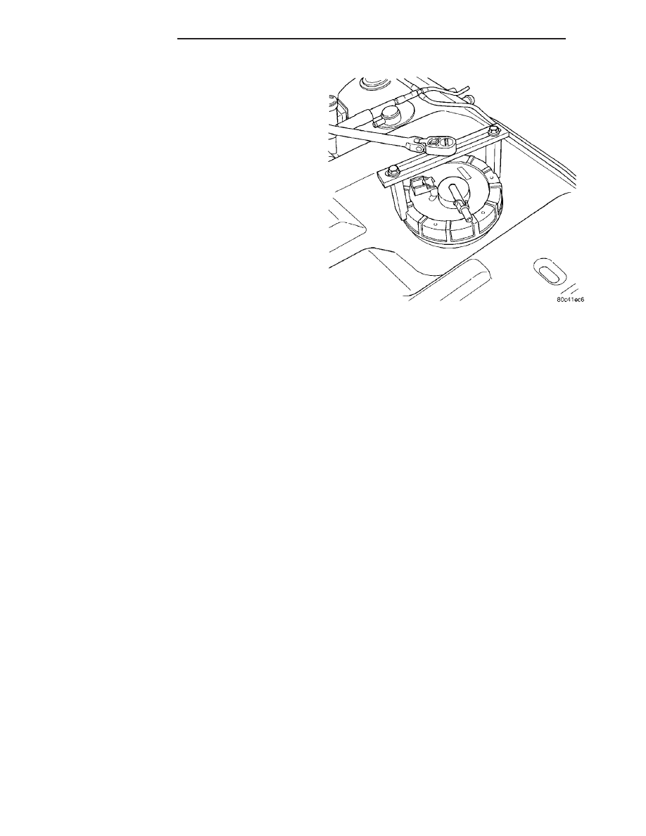
(9) Using Special Tool #6856 Fuel Pump Module

Ring Spanner, remove locknut to release pump mod-
ule (Fig. 10).

WARNING: THE FUEL RESERVOIR OF THE FUEL
PUMP MODULE DOES NOT EMPTY OUT WHEN THE
TANK IS DRAINED. THE FUEL IN THE RESERVOIR
MAY SPILL OUT WHEN THE MODULE IS REMOVED.
USE CAUTION TO AVOID PERSONAL INJURY.

(10) Remove fuel pump module and seal from

tank. Discard seal.

INSTALLATION

(1) Wipe seal area of tank clean. Place a new seal

between the tank threads and the pump module
opening.

NOTE: The pump has to properly located to the
tank for the fuel gauge to work properly.

(2) Position fuel pump module in tank. Make sure

the alignment marks line up on the fuel tank and
pump module.

CAUTION: Over tightening the pump lock ring may
result in a leak.

(3) While holding the pump module in position,

install locknut. Tighten locknut to 74.5 N·m (55 ft.
lbs) torque using special tool #6856.

(4) Install fuel tank, refer to the Fuel Tank Instal-

lation in this section.

(5) Lower vehicle.
(6) Install the negative battery cable.
(7) Install the air cleaner lid, connect the inlet air

temperature sensor and makeup air hose.

(8) Fill fuel tank with clean fuel. Use the DRBIII

t

scan tool to pressurize the system and check for
leaks.

FUEL RAIL

DESCRIPTION

The fuel rail supplies the necessary fuel to each

individual fuel injector and is mounted to the intake
manifold (Fig. 11).

Fig. 10 Fuel Pump Module Locknut

14 - 8

FUEL DELIVERY

PT

FUEL PUMP MODULE (Continued)

OPERATION

The fuel pressure regulator is no longer mounted

to the fuel rail on any engine. It is now located on
the fuel tank mounted fuel pump module. Refer to
Fuel Filter/Fuel Pressure Regulator in the Fuel
Delivery System section of this group for information.
The fuel rail is not repairable.

REMOVAL

REMOVAL

WARNING: RELEASE FUEL SYSTEM PRESSURE
BEFORE SERVICING FUEL SYSTEM COMPONENTS.
SERVICE VEHICLES IN WELL VENTILATED AREAS
AND AVOID IGNITION SOURCES. NEVER SMOKE
WHILE

SERVICING

THE

VEHICLE.

THIS

MAY

RESULT IN PERSONAL INJURY OR DEATH.

(1) Release fuel system pressure. Refer to Fuel

System Pressure Release procedure in this section.

(2) Remove the air cleaner lid, disconnect the inlet

air temperature sensor and makeup air hose.

(3) Remove the negative battery cable.
(4) Remove the engine cover or throttle control

shield if equipped.

NOTE: WRAP SHOP TOWELS AROUND HOSE TO
CATCH ANY GASOLINE SPILLAGE.

(5) Disconnect fuel supply tube from rail. Refer to

Quick-Connect Fittings in this section.

(6) Remove the Intake Manifold, refer to the

Engine section.

(7) Disconnect electrical connectors from fuel injec-

tors (Fig. 12).

(8) Remove bolts holding fuel rail (Fig. 13).
(9) Remove the fuel rail and injectors.
(10) Remove the injectors from the fuel rail.

REMOVAL - 2.4L TURBO

WARNING: RELEASE FUEL SYSTEM PRESSURE
BEFORE SERVICING FUEL SYSTEM COMPONENTS.
SERVICE VEHICLES IN WELL VENTILATED AREAS
AND AVOID IGNITION SOURCES. NEVER SMOKE
WHILE

SERVICING

THE

VEHICLE.

THIS

MAY

RESULT IN PERSONAL INJURY OR DEATH.

Fig. 11 Fuel Rail

Fig. 12 Fuel Injector

1 - FUEL INJECTOR
2 - FUEL TEST PORT

Fig. 13 Fuel Rail

PT

FUEL DELIVERY

14 - 9

FUEL RAIL (Continued)

(1) Release the fuel system pressure. Refer to Fuel

System Pressure Release procedure in this section.

(2) Disconnect the negative battery cable.
(3) Disconnect the throttle body inlet hose (Fig. 14)

and remove from throttle body.

(4) Disconnect the purge hose from the throttle

body (Fig. 14).

(5) Unlock and disconnect the electrical connection

at the throttle body (Fig. 14).

(6) Remove the throttle control shield (Fig. 15).

(7) Remove the throttle and speed control cables

from the throttle body.

(8) Remove the cables from the throttle body

bracket.

(9) Unlock and disconnect the MAP sensor electri-

cal connector (Fig. 16).

(10) Remove the vacuum lines from the rear of the

intake manifold (Fig. 17).

(11) Remove the 5 bolts from the front of the

intake manifold.

(12) Remove the 2 bolts from the rear of the intake

manifold (Fig. 17).

(13) Remove the intake manifold. Cover the lower

intake manifold openings (Fig. 18).

Fig. 14 THROTTLE BODY CONNECTIONS - 2.4L

TURBO

1 - Purge Hose
2 - Electrical Connections
3 - Inlet Hose

Fig. 15 THROTTLE CONTROL SHIELD - 2.4L TURBO

Fig. 16 MAP SENSOR - 2.4L TURBO

Fig. 17 VACUUM LINES - 2.4L TURBO

14 - 10

FUEL DELIVERY

PT

FUEL RAIL (Continued)

(14) Drain the Coolant system, refer to the Cooling

section for more information.

(15) Move the upper radiator hose clamp (Fig. 19),

so that the hose can be rotated up and out of the
way.

(16) Remove the 2 small hoses from the thermo-

stat housing (Fig. 20).

(17) Remove the 2 bolts from the thermostat hous-

ing (Fig. 21)and rotate the assembly up and out of
the way (Fig. 22).

NOTE: WRAP SHOP TOWELS AROUND HOSE TO
CATCH ANY GASOLINE SPILLAGE.

Fig. 18 LOWER INTAKE MANIFOLD - 2.4L TURBO

Fig. 19 UPPER RADIATOR HOSE CLAMP - 2.4L

TURBO

Fig. 20 SMALL HOSES AT HOUSING - 2.4L TURBO

Fig. 21 THERMOSTAT HOUSING - 2.4L TURBO

PT

FUEL DELIVERY

14 - 11

FUEL RAIL (Continued)


Content   ..  733  734  735  736   ..