Chrysler PT Cruiser. Manual - part 713


  Index      Chrysler     Chrysler PT Cruiser - service repair manual 2005 year


Search            


Content   ..  711  712  713  714   ..


Chrysler PT Cruiser. Manual - part 713


LEFT MOUNT

REMOVAL

(1) Remove air cleaner assembly.
(2) Disconnect negative cable from battery.
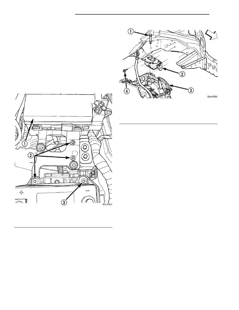
(3) Remove bolts attaching the power distribution

center (PDC) bracket to left mount and battery tray
(Fig. 99).

(4) Support transaxle with a suitable jack.
(5) Remove mount to transaxle bolts (Fig. 100).
(6) Remove left mount bracket to body frame rail

fasteners (Fig. 100).

(7) Remove mount.

INSTALLATION

(1) Install engine mount bracket to body frame rail

and tighten fasteners to 28 N·m (250 in. lbs.) (Fig.
100).

(2) Position engine/transaxle for installation of

mount to transaxle bolts. Install and tighten bolts to
68 N·m (50 ft. lbs.) (Fig. 100).

(3) Remove jack from under transaxle.
(4) Install bolts attaching the power distribution

center (PDC) bracket to left mount and battery tray
(Fig. 99).

(5) Connect negative cable to battery.
(6) Install air cleaner assembly.

RIGHT MOUNT

REMOVAL

(1) Remove the engine assembly for the required

clearance to access the engine mount (Refer to 9 -
ENGINE - REMOVAL).

NOTE: The right engine mount attaching holes are
slightly oversize to compensate for manufacturing
tolerances. The mount has been set at the manufac-
turing plant for proper powertrain alignment. There-
fore, it is necessary to mark the position of the
mount before the attaching bolts are loosened.

(2) Using a permanent ink marker or equivalent,

mark the position of engine mount to the body frame
rail.

(3) Remove bolts attaching mount to body (Fig.

101).

(4) Remove mount.

INSTALLATION

(1) Position mount into the original position on

body frame rail (Fig. 101).

NOTE: Engine mount must be installed in the origi-
nal position on body frame rail. If mount was not
marked or frame rail was replaced, perform the fol-
lowing procedure.

(2) Perform the following procedure if the mount

position was not previously marked, or the frame rail
was replaced:

(a) Insert new mount loosely in frame rail.

Fig. 99 PDC Bracket Attaching Bolts

1 - PDC
2 - PDC BRACKET BOLTS
3 - BATTERY TRAY BOLT

Fig. 100 Left Mount

1 - BOLT
2 - LEFT MOUNT
3 - TRANSAXLE
4 - BOLT

9 - 132

ENGINE 2.4L DOHC

PT

(b) Align the four holes in the mount with the

mating holes in the rail such that the holes are
concentric (frame rail holes centered in the mount
holes).

(c) Using a permanent ink marker or equivalent,

mark the position of engine mount to the body
frame rail while maintaining mounting hole con-
centricity.
(3) Ensure the mount maintains originally marked

position and install mount bolts. Tighten bolts to 28
N·m (250 in. lbs.) (Fig. 101).

(4) Install the engine assembly (Refer to 9 -

ENGINE - INSTALLATION).

TORQUE STRUT

REMOVAL

UPPER

(1) Remove bolts attaching upper torque strut to

shock tower bracket and engine mount bracket (Fig.
102).

(2) Remove timing belt front upper cover (if A/C

equipped).

(3) Remove the upper torque strut.

Fig. 102 Engine Mounting - Right Side

1 - BOLT
2 - RIGHT FENDER
3 - UPPER TORQUE STRUT BRACKET
4 - NUTS
5 - BOLT
6 - UPPER TORQUE STRUT

7 - BOLT
8 - LOWER TORQUE STRUT BRACKET
9 - BOLT
10 - LOWER TORQUE STRUT
11 - BOLT
12 - RIGHT ENGINE MOUNT

Fig. 101 Engine Mount—Right

1 - SNUBBER PAD
2 - RIGHT ENGINE MOUNT
3 - BOLTS

PT

ENGINE 2.4L DOHC

9 - 133

RIGHT MOUNT (Continued)

LOWER

(1) Raise vehicle on hoist.
(2) Remove accessory drive belt splash shield (Fig.

103).

(3) Remove pencil strut (Fig. 104).

(4) Remove bolts attaching lower torque strut to

crossmember and strut bracket (Fig. 102).

(5) Remove lower torque strut.

INSTALLATION

UPPER

(1) Position the upper torque strut into mounting

location (Fig. 102).

(2) Move torque strut aside (towards right fender)

and install timing belt front upper cover (if A/C
equipped).

(3) Install the torque strut mounting bolts and

perform the torque strut adjustment procedure (Refer
to

9

-

ENGINE/ENGINE

MOUNTING/TORQUE

STRUT - ADJUSTMENTS).

INSTALLATION - LOWER

(1) Position lower torque strut into mounting loca-

tions.

(2) Install mounting bolts and perform torque

strut adjustment procedure (Refer to 9 - ENGINE/
ENGINE MOUNTING/TORQUE STRUT - ADJUST-
MENTS).

(3) Install pencil strut and tighten nuts to 58 N·m

(43 ft. lbs.) (Fig. 104).

(4) Install accessory belt splash shield (Fig. 103)

and lower vehicle.

ADJUSTMENTS

ENGINE TORQUE STRUT ADJUSTMENT

The upper and lower torque struts need to be

adjusted together to assure proper engine positioning
and engine mount loading. Whenever a torque strut
bolt(s) is loosened, this procedure must be performed.

(1) Remove accessory drive belt splash shield (Fig.

103).

(2) Remove pencil strut (Fig. 104).
(3) Loosen the upper and lower torque strut

attaching bolt at the suspension crossmember and
shock tower bracket (Fig. 102).

(4) The engine position may now be adjusted by

positioning a suitable floor jack on the forward edge
of the transmission bell housing (Fig. 105).

NOTE: The floor jack must be positioned as shown
in (Fig. 105) to prevent minimal upward lifting of the
engine.

Fig. 103 Splash Shield

1 - RIGHT MOUNT BOLT ACCESS PLUG
2 - FASCIA
3 - SPLASH SHIELD
4 - CRANKSHAFT BOLT ACCESS PLUG

Fig. 104 Pencil Strut

1 - NUT
2 - PENCIL STRUT
3 - NUT
4 - FLAT WASHER
5 - LOWER TORQUE STRUT

9 - 134

ENGINE 2.4L DOHC

PT

TORQUE STRUT (Continued)

(5) With the engine supported, remove the upper

and lower torque strut attachment bolt(s) at shock
tower bracket and suspension crossmember (Fig.
102). Verify that the torque struts are free to move
within the shock tower bracket and crossmember.
Reinstall the torque strut bolt(s), but do not tighten.

(6) Carefully apply upward force, allowing the

upper engine to rotate rearward until the distance
between the center of the rearmost attaching bolt on
the engine mount bracket (point “A”) and the center
of the hole on the shock tower bracket (point “B”) is
119 mm (4.70 in.) (Fig. 106).

CAUTION: The engine must be held in position with
jack until both the upper and lower torque strut
bolts are tightened.

(7) With the engine held at the proper position,

tighten both the upper and lower torque strut bolts
to 115 N·m (85 ft. lbs.) (Fig. 102).

(8) Remove the floor jack.
(9) Install pencil strut and tighten nuts to 58 N·m

(43 ft. lbs.) (Fig. 104).

(10) Install accessory drive belt splash shield (Fig.

103).

LUBRICATION

DESCRIPTION

The lubrication system is a full-flow filtration,

pressure feed type. The oil pump is mounted in the
front engine cover and driven by the crankshaft.

OPERATION

Engine oil drawn up through the pickup tube and

is pressurized by the oil pump and routed through
the full-flow filter to the main oil gallery running the
length of the cylinder block. A diagonal hole in each
bulkhead feeds oil to each main bearing. Drilled pas-
sages within the crankshaft route oil from main bear-
ing journals to connecting rod journals. Balance shaft
lubrication is provided through an oil passage from
the number one main bearing cap through the bal-
ance shaft carrier support leg. This passage directly
supplies oil to the front bearings and internal
machined passages in the shafts that routes oil from
front to the rear shaft bearing journals. A vertical
hole at the number five bulkhead routes pressurized
oil through a restrictor (integral to the cylinder head
gasket) up past a cylinder head bolt to an oil gallery
running the length of the cylinder head. The cam-
shaft journals are partially slotted to allow a prede-
termined amount of pressurized oil to pass into the
bearing cap cavities. Lubrication of the camshaft
lobes are provided by small holes in the camshaft
bearing caps that are directed towards each lobe. Oil
returning to the pan from pressurized components
supplies lubrication to the valve stems. Cylinder
bores and wrist pins are splash lubricated from
directed slots on the connecting rod thrust collars.

DIAGNOSIS AND TESTING

CHECKING ENGINE OIL PRESSURE

(1) Disconnect and remove oil pressure switch.

(Refer to 9 - ENGINE/LUBRICATION/OIL PRES-
SURE SENSOR/SWITCH - REMOVAL)

(2) Install Special Tools C-3292 Gauge with 8406

Adaptor fitting.

Fig. 105 Floor Jack Positioning

1 - WOOD BLOCK
2 - FLOOR JACK

Fig. 106 Engine Position Measurement

PT

ENGINE 2.4L DOHC

9 - 135

TORQUE STRUT (Continued)


Content   ..  711  712  713  714   ..