Chrysler PT Cruiser. Manual - part 477


  Index      Chrysler     Chrysler PT Cruiser - service repair manual 2005 year


Search            


Content   ..  475  476  477  478   ..


Chrysler PT Cruiser. Manual - part 477


Replace any battery thermal guard that has been
damaged.

(5) Inspect the battery built-in test indicator sight

glass (if equipped) for an indication of the battery
condition. If the battery is discharged, charge as
required. Refer to Standard Procedures for detailed
instructions.

SPECIFICATIONS

SPECIFICATIONS

The battery Group Size number, the Cold Cranking

Amperage (CCA) rating, and the Reserve Capacity
(RC) rating or Ampere-Hours (AH) rating can be

found on the original equipment battery label. Be
certain that a replacement battery has the correct
Group Size number, as well as CCA, and RC or AH
ratings that equal or exceed the original equipment
specification for the vehicle being serviced. Battery
sizes and ratings are discussed in more detail below.

NOTE: Vehicles equipped with a diesel engine uti-
lize a unique battery. The specifications for this bat-
tery may differ from the standards shown here.
Refer to the battery manufacturer for detailed spec-
ifications.

• Group Size - The outside dimensions and ter-

minal placement of the battery conform to standards
established by the Battery Council International
(BCI). Each battery is assigned a BCI Group Size
number to help identify a correctly-sized replace-
ment.

• Cold Cranking Amperage - The Cold Crank-

ing Amperage (CCA) rating specifies how much cur-
rent (in amperes) the battery can deliver for thirty
seconds at -18° C (0° F). Terminal voltage must not
fall below 7.2 volts during or after the thirty second
discharge period. The CCA required is generally
higher as engine displacement increases, depending
also upon the starter current draw requirements.

• Reserve Capacity - The Reserve Capacity (RC)

rating specifies the time (in minutes) it takes for bat-
tery terminal voltage to fall below 10.5 volts, at a
discharge rate of 25 amperes. RC is determined with
the battery fully-charged at 26.7° C (80° F). This rat-
ing estimates how long the battery might last after a
charging system failure, under minimum electrical
load.

• Ampere-Hours - The Ampere-Hours (AH) rat-

ing specifies the current (in amperes) that a battery
can deliver steadily for twenty hours, with the volt-
age in the battery not falling below 10.5 volts. This
rating is also sometimes identified as the twenty-
hour discharge rating.

BATTERY CLASSIFICATIONS & RATINGS

Vehicle

Part Number

BCI Group

Size

Classification

Cold

Cranking

Amperage

Reserve

Capacity

Ampere -

Hours

Load Test

Amperage

PT 2.0/2.4L

04671579AB

26R

510

92 Minutes

50

255

PG 2.2L

Diesel

04868999AA

34

700

95 Minutes

48

350

PG 2.0L

05033315AA

45

510

80 Minutes

55

255

PG 1.6L

05033211AA

44

510

80 Minutes

50

255

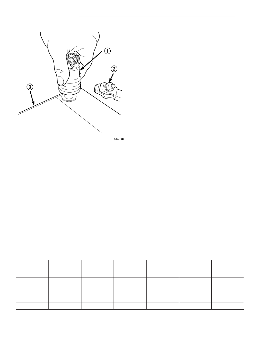
Fig. 3 Clean Battery Terminal Post - Typical

1 - TERMINAL BRUSH
2 - BATTERY CABLE
3 - BATTERY

8F - 6

BATTERY SYSTEM

PT

BATTERY SYSTEM (Continued)

TORQUE SPECIFICATIONS

DESCRIPTION

. . . . . . . . . . . . . . . . . . . . TORQUE

Battery Hold Down Bolt - Gasoline

Engine . . . . . . . . . . . . . . . . . . . . 110 ± 20 in. lbs.

Battery Hold Down Bolt - Diesel

Engine . . . . . . . . . . . . . . . . . . . . . 30 ± 10 ft. lbs.

Battery Cables . . . . . . . . . . . . . . . . 110 ± 20 in. lbs.

SPECIAL TOOLS

BATTERY SYSTEM SPECIAL TOOLS

BATTERY

DESCRIPTION

There are two different batteries available on this

model. Vehicles equipped with a diesel engine utilize
a spiral wound plate designed battery with recombi-
nation technology. This is a maintenance-free battery
that is capable of delivering more power than a con-
ventional battery. This additional power is required
by a diesel engine during cold cranking. Vehicles
equipped with a gasoline engine utilize a conven-
tional battery. Refer to the following information for
detailed differences and descriptions of these two bat-
teries.

SPIRAL PLATE BATTERY - DIESEL ENGINE

Spiral plate technology takes the elements of tradi-

tional batteries - lead and sulfuric acid - to the next
level. By tightly winding layers of spiral grids and
acid-permeated vitreous separators into cells, the
manufacturer has developed a battery with more
power and service life than conventional batteries the
same size. The spiral plate battery (Fig. 4) is com-
pletely, permanently sealed. Through gas recombina-
tion, hydrogen and oxygen within the battery are
captured during normal charging and reunited to
form the water within the electrolyte, eliminating the
need to add distilled water. Therefore, these batteries
have non-removable battery vent caps. Water cannot
be added to this battery.

The acid inside an spiral plate battery is bound

within the vitreous separators, ending the threat of
acid leaks. This feature allows the battery to be
installed in any position anywhere in the vehicle.

Spiral plate technology is the process by which the

plates holding the active material in the battery are
wound tightly in coils instead of hanging flat, like
conventional batteries. This design has a lower inter-
nal resistance and also increases the active material
surface area.

WARNING: NEVER EXCEED 14.4 VOLTS WHEN
CHARGING A SPIRAL PLATE BATTERY. PERSONAL
INJURY AND/OR BATTERY DAMAGE MAY RESULT.

Micro 420 Battery Tester

Fig. 4 PG Spiral Plate Battery

PT

BATTERY SYSTEM

8F - 7

BATTERY SYSTEM (Continued)

Due to the maintanance-free design, distilled water

cannot be added to this battery. Therefore, if more
than 14.4 volts are used during the spiral plate bat-
tery charging process, water vapor can be exhausted
through the pressure-sensitive battery vents and lost
for good. This can permanently damage the spiral
plate battery. Never exceed 14.4 volts when charging
a spiral plate battery. Personal injury and/or battery
damage may result.

CONVENTIONAL BATTERY - GASOLINE ENGINE

Low-maintenance conventional batteries are used

on vehicles equipped with a gasoline engine, these
batteries

have

non-removable

battery

cell

caps.

Under normal service, the composition of this battery
reduces gassing and water loss at normal charge
rates.

Conventional batteries (Fig. 5) are made up of six

individual cells that are connected in series. Each
cell contains positive charged plate groups made of
lead oxide, and negatively charged plate groups made
of sponge lead. The plates are submerged in a sulfu-
ric acid and water solution called electrolyte.

Both batteries are used to store electrical energy

potential in a chemical form. When an electrical load
is applied to the battery terminals, an electrochemi-
cal reaction occurs within the battery. This reaction
causes the battery to discharge electrical current.

OPERATION

The battery is designed to store electrical energy in

a chemical form. When an electrical load is applied to
the terminals of the battery, an electrochemical reac-
tion occurs. This reaction causes the battery to dis-
charge electrical current from its terminals. As the
battery discharges, a gradual chemical change takes
place within each cell. The chemical changes within
the battery are caused by the movement of excess or
free electrons between the positive and negative
plate groups. This movement of electrons produces a
flow of electrical current through the load device
attached to the battery terminals.

The battery is vented to release excess hydrogen

gas that is created when the battery is being charged
or discharged. However, even with these vents,
hydrogen gas can collect in or around the battery. If
hydrogen gas is exposed to flame or sparks, it may
ignite. If the battery is equipped with removable cell
caps, add distilled water whenever the electrolyte
level is below the top of the plates. If the battery cell
caps cannot be removed, the battery must be
replaced if the electrolyte level becomes low.

DIAGNOSIS AND TESTING - BATTERY

The battery must be completely charged and the

terminals should be properly cleaned and inspected
before diagnostic procedures are performed. Refer to
Battery System Cleaning for the proper cleaning pro-
cedures, and Battery System Inspection for the
proper battery inspection procedures. Refer to Stan-
dard Procedures for the proper battery charging pro-
cedures.

MICRO 420 BATTERY TESTER

The

Micro

420

automotive

battery

tester

is

designed to help the dealership technicians diagnose
the cause of a defective battery. Follow the instruc-
tion manual supplied with the tester to properly
diagnose a vehicle. If the instruction manual is not
available refer to the standard procedure in this sec-
tion, which includes the directions for using the
Micro 420 battery tester.

WARNING: IF THE BATTERY SHOWS SIGNS OF
FREEZING, LEAKING OR LOOSE POSTS, DO NOT
TEST, ASSIST-BOOST, OR CHARGE. THE BATTERY
MAY ARC INTERNALLY AND EXPLODE. PERSONAL
INJURY AND/OR VEHICLE DAMAGE MAY RESULT.

WARNING: EXPLOSIVE HYDROGEN GAS FORMS IN
AND AROUND THE BATTERY. DO NOT SMOKE,
USE FLAME, OR CREATE SPARKS NEAR THE BAT-
TERY. PERSONAL INJURY AND/OR VEHICLE DAM-
AGE MAY RESULT.

Fig. 5 Conventional Battery

1 - POSITIVE POST
2 - VENT
3 - TEST INDICATOR (IF EQUIPPED)
4 - VENT
5 - NEGATIVE POST
6 - PLATE GROUPS
7 - ELECTROLYTE LEVEL
8 - GREEN BALL
9 - BATTERY

8F - 8

BATTERY SYSTEM

PT

BATTERY (Continued)

WARNING: THE BATTERY CONTAINS SULFURIC
ACID, WHICH IS POISONOUS AND CAUSTIC. AVOID
CONTACT WITH THE SKIN, EYES, OR CLOTHING.
IN THE EVENT OF CONTACT, FLUSH WITH WATER
AND CALL A PHYSICIAN IMMEDIATELY. KEEP OUT
OF THE REACH OF CHILDREN.

A battery that will not accept a charge is faulty,

and

must

be

replaced.

Further

testing

is

not

required. A fully-charged battery must be tested to
determine its cranking capacity. A battery that is ful-
ly-charged, but does not pass the Micro 420 or load
test, is faulty and must be replaced.

NOTE: Completely discharged batteries may take
several hours to accept a charge. Refer to Standard
Procedures for the proper battery charging proce-
dures.

STANDARD PROCEDURE

STANDARD PROCEDURE - SPIRAL PLATE
BATTERY CHARGING

Vehicles equipped with a diesel engine utilize a

unique spiral plate battery. This battery has a maxi-
mum charging voltage that must not be exceeded in
order to restore the battery to its full potential, fail-
ure to use the following spiral plate battery charging
procedure could result in damage to the battery or
personal injury.

Battery charging is the means by which the bat-

tery can be restored to its full voltage potential. A
battery is fully-charged when:

• Micro 420 battery tester indicates battery is OK.

• Open-circuit voltage of the battery is 12.65 volts

or above.

• Battery passes Load Test multiple times.

WARNING: IF THE BATTERY SHOWS SIGNS OF
FREEZING, LEAKING, LOOSE POSTS OR LOW
ELECTROLYTE LEVEL, DO NOT TEST, ASSIST-
BOOST, OR CHARGE. THE BATTERY MAY ARC
INTERNALLY AND EXPLODE. PERSONAL INJURY
AND/OR VEHICLE DAMAGE MAY RESULT.

CAUTION: Always disconnect and isolate the bat-
tery negative cable before charging a battery.
Charge the battery directly at the battery terminals.
Do not exceed 14.4 volts while charging a battery.

CAUTION: The battery should not be hot to the
touch. If the battery feels hot to the touch, turn off
the charger and let the battery cool before continu-
ing the charging operation. Damage to the battery
may result.

After the battery has been charged to 12.6 volts or

greater, perform a load test to determine the battery
cranking capacity. Refer to Battery Diagnosis and
Testing for the proper battery test procedures. If the
battery will endure a load test, return the battery to
service. If the battery will not pass a load test, it is
faulty and must be replaced.

Clean and inspect the battery hold downs, tray,

terminals, posts, and top before completing battery
service. Refer to Battery System Cleaning for the
proper battery system cleaning procedures, and Bat-
tery System Inspection for the proper battery system
inspection procedures.

CHARGING A COMPLETELY DISCHARGED
BATTERY – SPIRAL PLATE BATTERY

The following procedure should be used to recharge

a completely discharged battery. Unless this proce-
dure is properly followed, a good battery may be
needlessly replaced.

(1) Measure the voltage at the battery posts with a

voltmeter, accurate to 1/10 (0.10) volt (Fig. 6). Refer
to Battery Removal and Installation for access
instructions. If the reading is below ten volts, the
battery charging current will be low. It could take
several hours before the battery accepts a current
greater than a few milliamperes. Such low current
may not be detectable on the ammeters built into
many battery chargers.

Fig. 6 Voltmeter - Typical

PT

BATTERY SYSTEM

8F - 9

BATTERY (Continued)


Content   ..  475  476  477  478   ..