Chrysler PT Cruiser. Manual - part 469


  Index      Chrysler     Chrysler PT Cruiser - service repair manual 2005 year


Search            


Content   ..  467  468  469  470   ..


Chrysler PT Cruiser. Manual - part 469


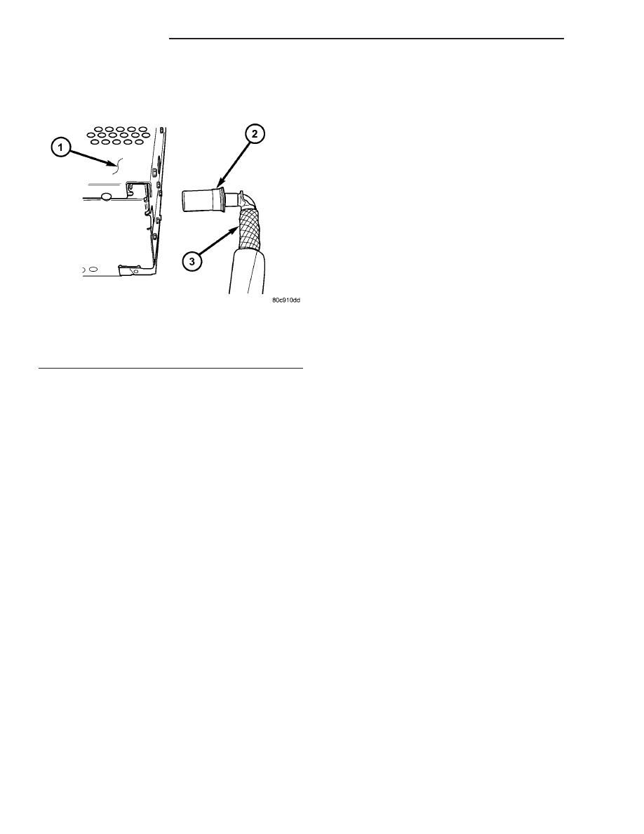
(5) Disconnect the antenna cable by pulling the

locking antenna connector away from the radio (Fig.
9).

INSTALLATION

(1) Connect

the

wire

harness

connector

and

antenna cable to radio.

(2) Insert radio into instrument panel.
(3) Install mounting fasteners. Tighten to 2 N·m

(20 in. lbs.).

(4) Install instrument panel center bezel.
(5) Connect battery negative cable.

RADIO NOISE SUPPRESSION
COMPONENTS

DESCRIPTION

Radio noise suppression devices are factory-in-

stalled standard equipment on this vehicle. Radio
Frequency Interference (RFI) and ElectroMagnetic
Interference (EMI) can be produced by any on-board
or external source of electromagnetic energy. These
electromagnetic energy sources can radiate electro-
magnetic signals through the air, or conduct them
through the vehicle electrical system.

When the audio system converts RFI or EMI to an

audible acoustic wave form, it is referred to as radio
noise. This undesirable radio noise is generally man-
ifested in the form of “buzzing,” “hissing,” “popping,”
“clicking,” “crackling,” and/or “whirring” sounds. In
most cases, RFI and EMI radio noise can be sup-
pressed using a combination of vehicle and compo-
nent grounding, filtering and shielding techniques.
This vehicle is equipped with factory-installed radio
noise suppression devices that were designed to min-

imize exposure to typical sources of RFI and EMI;
thereby, minimizing radio noise complaints.

Radio noise suppression is accomplished primarily

through circuitry or devices that are integral to the
radios, audio power amplifiers and other on-board
electrical components such as generators, wiper
motors, blower motors, and fuel pumps that have
been found to be potential sources of RFI or EMI.
External radio noise suppression devices that are
used on this vehicle to control RFI or EMI, and can
be serviced, include the following:

• Ground straps - This length of braided ground

strap has an eyelet terminal connector crimped to
each end. They are located in various locations on
the vehicle.

• Radio Noise Suppression Capacitor - This

component is attached near the exhaust manifold.

• Resistor-type spark plugs - This type of spark

plug has an internal resistor connected in series
between the spark plug terminal and the center elec-
trode to help reduce the production of electromag-
netic radiation that can result in radio noise.

OPERATION

There are two common strategies that can be used

to suppress Radio Frequency Interference (RFI) and
ElectroMagnetic Interference (EMI) radio noise. The
first suppression strategy involves preventing the
production of RFI and EMI electromagnetic signals
at their sources. The second suppression strategy
involves preventing the reception of RFI and EMI
electromagnetic signals by the audio system compo-
nents.

The use of braided ground straps in key locations

is part of the RFI and EMI prevention strategy.
These ground straps ensure adequate ground paths,
particularly for high current components such as
many of those found in the starting, charging, igni-
tion, engine control and transmission control sys-
tems. An insufficient ground path for any of these
high current components may result in radio noise
caused by induced voltages created as the high cur-
rent seeks alternative ground paths through compo-
nents or circuits intended for use by, or in close
proximity to the audio system components or circuits.

Preventing the reception of RFI and EMI is accom-

plished by ensuring that the audio system compo-
nents are correctly installed in the vehicle. Loose,
corroded or improperly soldered wire harness connec-
tions, improperly routed wiring and inadequate audio
system component grounding can all contribute to
the reception of RFI and EMI. A properly grounded
antenna body and radio chassis, as well as a shielded
antenna coaxial cable with clean and tight connec-
tions will each help reduce the potential for reception
of RFI and EMI.

Fig. 9 ANTENNA TO RADIO

1 - RADIO
2 - LOCKING ANTENNA CONNECTOR
3 - INSTRUMENT PANEL ANTENNA CABLE

8A - 12

AUDIO/VIDEO

PT

RADIO (Continued)

REMOVAL

ENGINE GROUND STRAP

(1) Disconnect and isolate the battery negative

cable.

(2) Remove bolt from engine cylinder head (Fig.

10), (Fig. 11), (Fig. 12).

(3) Remove bolt from strut tower and remove strap

(Fig. 13).

HOOD HINGE GROUND STRAP

(1) Disconnect and isolate the battery negative

cable.

(2) Remove bolt from fender (Fig. 14).
(3) Remove bolt from hood and remove strap.

Fig. 10 GROUND STRAP TO ENGINE 1.6L

Fig. 11 GROUND STRAP TO ENGINE 2.0/2.4L

Fig. 12 GROUND STRAP TO ENGINE 2.2L

Fig. 13 GROUND STRAP TO STRUT TOWER

Fig. 14 HOOD HINGE GROUND STRAP

PT

AUDIO/VIDEO

8A - 13

RADIO NOISE SUPPRESSION COMPONENTS (Continued)

MUFFLER GROUND STRAP

(1) Disconnect and isolate the battery negative

cable.

(2) Remove bolt from rear floor pan (Fig. 15).

(3) Remove bolt from muffler and remove strap.

RADIO NOISE SUPPRESSION CAPACITOR

(1) Disconnect and isolate the battery negative

cable.

(2) Disconnect electrical harness connector from

capacitor (Fig. 16).

(3) Remove bolt from capacitor and remove capac-

itor.

STRUT BRACKET TO BODY GROUND STRAP

(1) Disconnect and isolate the battery negative

cable.

(2) Remove bolt from strut (Fig. 17)

(3) Remove strap from frame rail.

INSTALLATION

ENGINE GROUND STRAP

(1) Install strap and bolt to strut tower. Tighten

bolt to 12 N·m (105 in. lbs.).

(2) Install strap and bolt to engine cylinder head.

Tighten bolt to 28 N·m (21 ft. lbs.).

(3) Connect battery negative cable.

HOOD HINGE GROUND STRAP

(1) Install strap and bolt to fender. Tighten bolt to

4 N·m (35 in. lbs.).

(2) Install strap and bolt to hood. Tighten bolt to 4

N·m (35 in. lbs.).

(3) Connect battery negative cable.

MUFFLER GROUND STRAP

(1) Install strap and bolt to rear floor pan. Tighten

bolt to 8 N·m (75 in. lbs.).

(2) Install strap and bolt to muffler. Tighten bolt to

8 N·m (75 in. lbs.).

(3) Connect battery negative cable.

RADIO NOISE SUPPRESSION CAPACITOR

(1) Install capacitor and bolt.
(2) Connect electrical harness connector to capaci-

tor.

(3) Connect battery negative cable.

STRUT BRACKET TO BODY GROUND STRAP

(1) Install strap to frame rail.

CAUTION: Ensure that ground strap does not come
in contact with brake hose. Damage to brake hose
can result.

Fig. 15 MUFFLER GROUND STRAP

Fig. 16 RADIO NOISE CAPACITOR - TYPICAL

1 - RADIO NOISE CAPACITOR
2 - EXHAUST MANIFOLD

Fig. 17 STRUT BRACKET TO BODY GROUND

STRAP

8A - 14

AUDIO/VIDEO

PT

RADIO NOISE SUPPRESSION COMPONENTS (Continued)

(2) Install strap and bolt to strut. Tighten bolt to

12 N·m (105 in. lbs.).

(3) Connect battery negative cable.

SATELLITE RECEIVER
MODULE

DESCRIPTION

The satellite receiver module is located behind the

left rear trim panel. It is mounted to a bracket which
is fastened to the inner quarter panel sheet metal.

OPERATION

The satellite receiver module receives signals from

the roof mounted antenna and processes this infor-
mation before it is sent to the radio. The module
operates on both battery and accessory feed circuits
and will operate with the ignition key in the run or
accessory position only.

REMOVAL

NOTE:
If the owner’s satellite service was active before the
satellite receiver module was replaced the new sat-
ellite receiver module will have to be activated. The
existing satellite receiver module will have to be
deactivated before the replacement satellite receiver
module can be activated.
To activate Sirius satellite radio service, call Sirius
at their toll-free number. Please have the following
information available when activating a system:

Electronic Serial Number / Sirius Identification

Number (ESN/SID) of the unit to be replaced

ESN/SID of the replacement receiver

Vehicle Owner’s name and address

VIN

The ESN/SID number can be obtained through the
radio display by following the steps in the satellite
radio owners manual.
The vehicle must be outside with the audio system
powered on, in the satellite radio mode, to receive
the activation signal.

(1) Disconnect and isolate the battery negative

cable.

(2) Remove the left rear quarter trim panel (Refer

to 23 - BODY/INTERIOR/LEFT QUARTER TRIM
PANEL - REMOVAL).

(3) Remove the mounting bracket fasteners (Fig.

18).

(4) Disconnect the wire harness connectors.
(5) Remove the module from the mounting bracket.

INSTALLATION

NOTE:
If the owner’s satellite service was active before the
satellite receiver module was replaced the new sat-
ellite receiver module will have to be activated. The
existing satellite receiver module will have to be
deactivated before the replacement satellite receiver
module can be activated.
To activate Sirius satellite radio service, call Sirius
at their toll-free number. Please have the following
information available when activating a system:

Electronic Serial Number / Sirius Identification

Number (ESN/SID) of the unit to be replaced

ESN/SID of the replacement receiver

Vehicle Owner’s name and address

VIN

The ESN/SID number can be obtained through the
radio display by following the steps in the satellite
radio owners manual.
The vehicle must be outside with the audio system
powered on, in the satellite radio mode, to receive
the activation signal.

(1) Position the module to the mounting bracket.

Tighten mounting fasteners to 6 N·m (53 in. lbs.).

(2) Connect wire harness connectors.
(3) Install

mounting

bracket

and

fasteners.

Tighten to 5 N·m (45 in. lbs.).

(4) Install the left rear quarter trim panel (Refer

to 23 - BODY/INTERIOR/LEFT QUARTER TRIM
PANEL - INSTALLATION).

(5) Connect the battery negative cable.

Fig. 18 SATELLITE RECEIVER MODULE

1 - SATELLITE RECEIVER MODULE
2 - MOUNTING BRACKET FASTENERS

PT

AUDIO/VIDEO

8A - 15

RADIO NOISE SUPPRESSION COMPONENTS (Continued)


Content   ..  467  468  469  470   ..