Chrysler PT Cruiser. Manual - part 449


  Index      Chrysler     Chrysler PT Cruiser - service repair manual 2005 year


Search            


Content   ..  447  448  449  450   ..


Chrysler PT Cruiser. Manual - part 449


DIESEL AND TURBO MODELS

The clutch release system utilizes a slave cylinder

of a concentric design, having all components fixed
about the same axis. The concentric slave cylinder
(CSC) is mounted to the inside of the clutch bellhous-
ing (Fig. 85), and is serviced only as an assembly.

The concentric design permits high efficiency,

resulting in low and consistent pedal effort, as well
as automatic adjustment to compensate for clutch
disc wear.

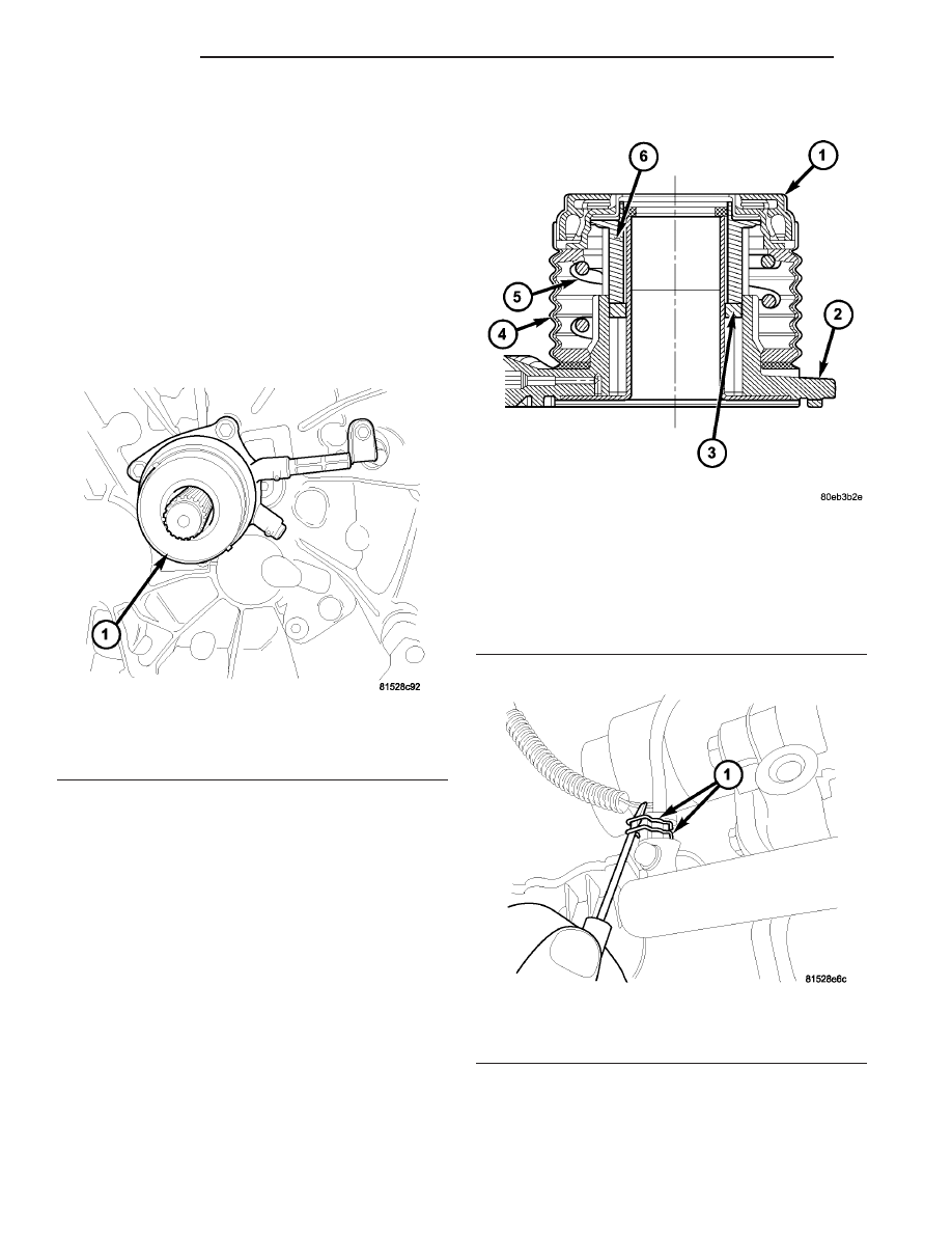
The CSC is a self-contained unit, consisting of a

main body and piston, spring, integrated release
bearing, and a rubber boot (Fig. 86).

REMOVAL

REMOVAL—1.6/2.4L (Except Diesel and
Turbo)

NOTE: To prevent drainage of clutch master cylin-
der assembly upon slave cylinder removal, it is nec-
essary to make sure brake master cylinder fluid
level is full and reservoir cap is installed tight.

(1) Verify proper brake fluid level and top off if

necessary. Install and tighten brake master cylinder
cap to prevent clutch hydraulic system drainage.

(2) Raise vehicle on hoist.
(3) Using suitable screwdriver, release both slave

cylinder hydraulic line snap ring retainers (Fig. 87).
Do not separate at this time.

Fig. 85 Slave Cylinder Location—Diesel and Turbo

Models

1 - CONCENTRIC SLAVE CYLINDER (CSC)

Fig. 86 Concentric Slave Cylinder (CSC)

Components

1 - RELEASE BEARING
2 - BODY
3 - SEAL
4 - BOOT
5 - SPRING
6 - PISTON

Fig. 87 Hydraulic Tube Retainer Clips

1 - RETAINER CLIPS

6 - 40

CLUTCH

PT

SLAVE CYLINDER (Continued)

(4) Remove slave cylinder-to-transaxle mounting

bolts (Fig. 88) (Fig. 89).

(5) Have replacement slave cylinder ready. Remove

slave cylinder from transaxle and separate from
hydraulic tube. Quickly attach replacement slave cyl-
inder to plumbing and secure with both retaining
clips.

REMOVAL—DIESEL AND TURBO MODELS

NOTE: To prevent drainage of clutch master cylin-
der assembly upon slave cylinder removal, it is nec-
essary to make sure brake master cylinder fluid
level is full and reservoir cap is installed tight.

(1) Remove transaxle from vehicle. (Refer to 21 -

TRANSMISSION/TRANSAXLE/MANUAL

-

REMOVAL)

(2) Remove four (4) slave cylinder-to-clutch bell-

housing bolts and remove slave cylinder from trans-
axle (Fig. 90).

INSTALLATION

INSTALLATION—1.6/2.4L MODELS (Except
Diesel and Turbo)

(1) Connect slave cylinder to hydraulic tube. Press

both retainer clips to secure tube in cylinder (Fig. 91).

Fig. 88 Clutch Slave Cylinder at Transaxle—1.6L

Models

1 - SLAVE CYLINDER
2 - BOLT

Fig. 89 Clutch Slave Cylinder at Transaxle—2.4L

Models

1 - SLAVE CYLINDER
2 - BRACKET

Fig. 90 CSC Removal/Installation

1 - CONCENTRIC SLAVE CYLINDER

Fig. 91 Hydraulic Tube Retaining Clips

1 - RETAINER CLIPS

PT

CLUTCH

6 - 41

SLAVE CYLINDER (Continued)

(2) Install the slave cylinder assembly into position

on transaxle (Fig. 92) (Fig. 93).

(3) Tighten slave cylinder-to-transaxle bolts to 19

N·m (168 in. lbs.) on 2.4L applications, and 12 N·m
(105 in. lbs.) torque on 1.6L applications.

(4) Lower vehicle.
(5) Verify brake master cylinder reservoir is full.

Top off with DOT 3 brake fluid if necessary.

(6) Bleed clutch hydraulic system (Refer to 6 -

CLUTCH - STANDARD PROCEDURE).

(7) Verify proper clutch release system operation.

INSTALLATION—DIESEL AND TURBO MODELS

(1) Install slave cylinder to transaxle using new

bolts (Fig. 94).

NOTE: Torque three CSC body screws first, then
fluid tube attachment.

(2) Torque slave cylinder-to-case bolts in three

steps:

1. 2 N·m (18 in. lbs.)
2. 5 N·m (44 in. lbs.)
3. 8.4 N·m (74 in. lbs.)
(3) Install transaxle. (Refer to 21 - TRANSMIS-

SION/TRANSAXLE/MANUAL - INSTALLATION)

(4) Bleed clutch hydraulic system. (Refer to 6 -

CLUTCH - STANDARD PROCEDURE)

Fig. 92 Clutch Slave Cylinder at Transaxle—1.6L

Models

1 - SLAVE CYLINDER
2 - BOLT

Fig. 93 Clutch Slave Cylinder at Transaxle—2.4L

Models

1 - SLAVE CYLINDER
2 - BRACKET

Fig. 94 CSC Removal/Installation

1 - CONCENTRIC SLAVE CYLINDER

6 - 42

CLUTCH

PT

SLAVE CYLINDER (Continued)

COOLING

TABLE OF CONTENTS

page

page

COOLING

WARNING

COOLING SYSTEM WARNINGS

. . . . . . . . . . . 1

SPECIFICATIONS

TORQUE - 1.6L SOHC

. . . . . . . . . . . . . . . . . . . 1

TORQUE - 2.0/2.4L

. . . . . . . . . . . . . . . . . . . . . 2

SPECIAL TOOLS

COOLING SYSTEM

. . . . . . . . . . . . . . . . . . . . . 2

ACCESSORY DRIVE - 1.6L SOHC

. . . . . . . . . . . . 3

ACCESSORY DRIVE - 2.0/2.4L DOHC

. . . . . . . . . 7

ENGINE - 1.6L SOHC

. . . . . . . . . . . . . . . . . . . . . 13

ENGINE - 2.0/2.4L DOHC

. . . . . . . . . . . . . . . . . . 33

TRANSMISSION

. . . . . . . . . . . . . . . . . . . . . . . . . 64

COOLING

WARNING

COOLING SYSTEM WARNINGS

WARNING: ANTIFREEZE IS AN ETHYLENE GLYCOL
BASED COOLANT AND IS HARMFUL IF SWAL-
LOWED OR INHALED. IF SWALLOWED, DRINK
TWO GLASSES OF WATER AND INDUCE VOMIT-
ING. IF INHALED, MOVE TO FRESH AIR AREA.
SEEK MEDICAL ATTENTION IMMEDIATELY. DO NOT
STORE IN OPENED OR UNMARKED CONTAINERS.
WASH SKIN AND CLOTHING THOROUGHLY AFTER
COMING IN CONTACT WITH ETHYLENE GLYCOL.
KEEP OUT OF REACH OF CHILDREN AND PETS.
DISPOSE OF GLYCOL BASED COOLANT PROP-
ERLY, CONTACT YOUR DEALER OR GOVERNMENT
AGENCY FOR LOCATION OF COLLECTION CENTER
IN YOUR AREA. DO NOT OPEN A COOLING SYS-
TEM WHEN THE ENGINE IS AT OPERATING TEM-
PERATURE

OR

HOT

UNDER

PRESSURE,

PERSONAL INJURY CAN RESULT. AVOID RADIA-
TOR COOLING FAN WHEN ENGINE COMPARTMENT
RELATED SERVICE IS PERFORMED, PERSONAL
INJURY CAN RESULT.

SPECIFICATIONS

TORQUE - 1.6L SOHC

DESCRIPTION

N·m

Ft.

Lbs.

In.

Lbs.

Screws, A/C Condenser to
Radiator

8

70

Fasteners, Accessory Drive
Belt Tensioner

12

105

Nut/Screw, Coolant Recovery
Container

4

35

Coolant Temperature Sensor

17

150

Fastener, Idler Pulley

28

250

Screws, Radiator Fan to
Radiator

6

55

Screws, Thermostat Housing

7

65

Bolts, Water Pump/Power
Steering Pump to Engine
Block

28

21

PT

COOLING

7 - 1


Content   ..  447  448  449  450   ..