Chrysler PT Cruiser. Manual - part 434


  Index      Chrysler     Chrysler PT Cruiser - service repair manual 2005 year


Search            


Content   ..  432  433  434  435   ..


Chrysler PT Cruiser. Manual - part 434


output of the sensor, sent to the CAB, is a DC volt-
age signal with changing voltage and current levels.
The ground for the IC and the current sense circuit
is provided by the CAB/ABM.

When a valley of the tone wheel is aligned with the

sensor, the voltage signal is approximately 0.8 volts
and a constant 7 mA current is sent to the CAB/
ABM. As the tone wheel rotates, the tooth shifts the
magnetic field and the IC enables a second 7 mA cur-
rent source. The CAB/ABM senses a voltage signal of
approximately 1.6 volts and 14 mA. The CAB/ABM
measures the amperage of the digital signal for each
wheel. The resulting signal is interpreted by the
CAB/ABM as the wheel speed.

REMOVAL

NOTE: Before proceeding, (Refer to 5 - BRAKES -
WARNING) (Refer to 5 - BRAKES - CAUTION).

(1) Raise the vehicle. (Refer to LUBRICATION &

MAINTENANCE/HOISTING - STANDARD PROCE-
DURE).

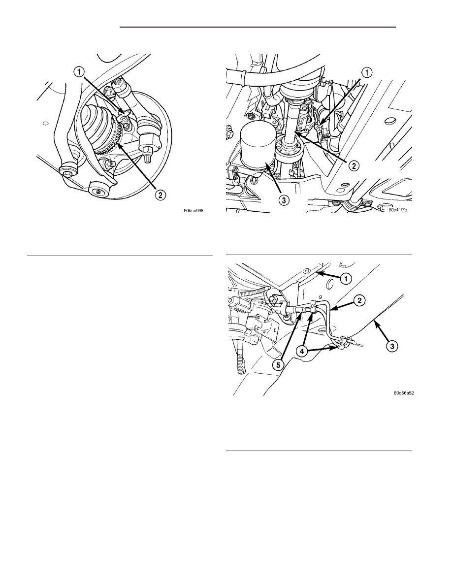
(2) Disconnect the wheel speed sensor cable con-

nector from the wiring harness on the inside of the
frame rail above the front suspension crossmember
(Fig. 5). The connector has a locking tab which that
must be pulled back before the connector release
tang can be depressed, releasing the connection.

(3) If the sensor being removed is a left front,

unclip the speed sensor cable from the brake tube on
the inside of and under the frame rail (Fig. 6).

(4) Remove the speed sensor cable grommet from

the retaining bracket attached to the brake hose on
the outside of the frame rail.

(5) Remove the bolt mounting the wheel speed sen-

sor head to the steering knuckle (Fig. 7).

Fig. 4 Right Front Wheel Speed Sensor (Heat Shield

Not Shown)

1 - RIGHT FRONT WHEEL SPEED SENSOR
2 - TONE WHEEL

Fig. 5 Wiring Harness Connector

1 - RIGHT FRONT WHEEL SPEED SENSOR CONNECTOR
2 - RIGHT FRONT DRIVESHAFT
3 - ENGINE OIL FILTER

Fig. 6 Left Sensor Routing Along Brake Tube

1 - ABS ICU
2 - BRAKE TUBE
3 - FRAME RAIL
4 - ROUTING CLIPS
5 - WHEEL SPEED SENSOR CABLE

5 - 88

BRAKES - ABS

PT

FRONT WHEEL SPEED SENSOR (Continued)

CAUTION: When removing a wheel speed sensor
from the knuckle, do not use pliers on the sensor
head. This may damage the sensor head. If the sen-
sor has seized, use a hammer and a punch to tap
the edge of the sensor head ear, rocking the sensor
side-to-side until free.

(6) Carefully, remove the sensor head and heat

shield from the steering knuckle.

(7) Remove the screw securing the wheel speed

sensor to the rear of the strut (Fig. 8). Remove the
wheel speed sensor.

INSTALLATION

CAUTION: Failure to install speed sensor cables
properly may result in contact with moving parts or
an over extension of cables causing an open cir-
cuit. Be sure that cables are installed, routed, and
clipped properly.

(1) Attach the wheel speed sensor to the strut

using the its mounting screw (Fig. 8).

(2) Install the wheel speed sensor head in the

steering knuckle (Fig. 7). Install the mounting bolt.
Tighten the mounting bolt to a torque of 12 N·m (105
in. lbs.).

(3) From the sensor bracket on the strut, loop the

sensor cable upward, then downward at the outside
of the frame rail. Install the speed sensor cable grom-
met onto the retaining bracket attached to the brake
hose on the outside of the frame rail.

(4) Loop the wheel speed sensor cable around the

bottom of the frame rail and connect it to the wiring
harness connector on the inside of the frame rail
(Fig. 5). Remember to push in the locking tab on the
connector.

(5) If the sensor being installed is the left front,

clip the speed sensor cable to the brake tube on the
inside of and under the frame rail (Fig. 6).

(6) Install the tire and wheel assembly. Progres-

sively tighten wheel mounting nuts to 135 N·m (100
ft. lbs.).

(7) Lower the vehicle.
(8) Road test vehicle to ensure proper operation of

the base brakes and ABS.

REAR WHEEL SPEED SENSOR

DESCRIPTION

The antilock brake system uses two-wire wheel

speed sensors, known as active wheel speed sensors.
The sensors use an electronic principle known as
magnetoresistive to help increase performance and
durability. The sensors convert wheel speed into a
small digital signal. A wheel speed sensor (WSS) is
used at each wheel. The gear (tooth) type tone wheel
serves as the trigger mechanism for each sensor. At
each wheel of the vehicle there is one wheel speed
sensor and one tone wheel.

The rear wheel speed sensors are mounted through

the disc brake adapter (Fig. 9) (Fig. 10) or drum
brake support plate. The rear tone wheels are
mounted to and rotate with the hub and bearing
assemblies.

The WSS air gaps are not adjustable. For the WSS

air gap specification, (Refer to 5 - BRAKES - ABS -
SPECIFICATIONS). Each WSS is serviced individu-

Fig. 7 Wheel Speed Sensor (Heat Shield Not Shown)

1 - RIGHT FRONT WHEEL SPEED SENSOR
2 - TONE WHEEL

Fig. 8 Wheel Speed Sensor At Strut

1 - ABS WHEEL SPEED SENSOR ROUTING BRACKET (IF
EQUIPPED)
2 - GROUND STRAP
3 - GROUND STRAP SCREW
4 - ABS SENSOR BRACKET SCREW (IF EQUIPPED)

PT

BRAKES - ABS

5 - 89

FRONT WHEEL SPEED SENSOR (Continued)

ally. The tone wheels are serviced as an assembly
with the hub and bearing assemblies.

OPERATION

The CAB (MK20e) or ABM (MK25e) sends 12 volts

to power an Integrated Circuit (IC) in the sensor. The
IC supplies a constant 7 mA power supply to the
CAB/ABM. The relationship of the tooth on the tone
wheel to the permanent magnet in the sensor, signals
the IC to enable a second 7 mA power supply. The
output of the sensor, sent to the CAB/ABM, is a DC
voltage signal with changing voltage and current lev-

els. The ground for the IC and the current sense cir-
cuit is provided by the CAB/ABM.

When a valley of the tone wheel is aligned with the

sensor, the voltage signal is approximately 0.8 volts
and a constant 7 mA current is sent to the CAB/
ABM. As the tone wheel rotates, the tooth shifts the
magnetic field and the IC enables a second 7 mA cur-
rent source. The CAB/ABM senses a voltage signal of
approximately 1.6 volts and 14 mA. The CAB/ABM
measures the amperage of the digital signal for each
wheel. The resulting signal is interpreted by the
CAB/ABM as the wheel speed.

REMOVAL

NOTE: Before proceeding, (Refer to 5 - BRAKES -
WARNING) (Refer to 5 - BRAKES - CAUTION).

(1) Raise the vehicle. (Refer to LUBRICATION &

MAINTENANCE/HOISTING - STANDARD PROCE-
DURE).

(2) Remove the tire and wheel assembly from the

vehicle.

(3) Disconnect the wheel speed sensor cable con-

nector from the vehicle wiring harness (Fig. 11).
Remove the clip attaching wheel speed sensor cable
connector to the vehicle’s body.

(4) Disconnect the wheel speed sensor cable rout-

ing clips running along the brake tube, brake hose
and axle trailing arm.

Fig. 9 Left Rear Wheel Speed Sensor

1 - LEFT REAR WHEEL SPEED SENSOR
2 - SHOCK ABSORBER

Fig. 10 Right Rear Wheel Speed Sensor

1 - SHOCK ABSORBER
2 - RIGHT REAR WHEEL SPEED SENSOR

Fig. 11 Wheel Speed Sensor Connector

1 - RIGHT REAR WHEEL SPEED SENSOR CONNECTOR
2 - FUEL TANK
3 - EVAPORATIVE CANISTER

5 - 90

BRAKES - ABS

PT

REAR WHEEL SPEED SENSOR (Continued)

CAUTION: When removing a wheel speed sensor
from the rear disc brake adapter, do not use pliers
on the sensor head. This may damage the sensor
head. If the sensor has seized, use a hammer and a
punch to tap the edge of the sensor head ear, rock-
ing the sensor side-to-side until free.

(5) Remove the bolt attaching the wheel speed sen-

sor to the rear disc brake adapter or drum brake sup-
port plate (Fig. 12), then carefully remove the sensor
head from the rear disc brake adapter and vehicle.

INSTALLATION

CAUTION: Failure to install speed sensor cables
properly may result in contact with moving parts or
an over extension of cables causing an open cir-
cuit. Be sure that cables are installed, routed, and
clipped properly.

(1) Install the wheel speed sensor head into the

disc brake adapter or drum brake support plate (Fig.
12).

(2) Install the wheel speed sensor mounting bolt.

Tighten the mounting bolt to a torque of 12 N·m (105
in. lbs.).

(3) Install wheel speed sensor cable into the rout-

ing clips on the brake tube, brake hose and axle
trailing arm.

(4) Connect the wheel speed sensor cable connector

into vehicle wiring harness (Fig. 11). Install the clip
attaching the wheel speed sensor cable connector to
vehicle’s body.

(5) Install the tire and wheel assembly on vehicle.

Progressively tighten wheel mounting nuts to 135
N·m (100 ft. lbs.).

(6) Lower the vehicle.
(7) Road test the vehicle to ensure proper opera-

tion of the base brakes and ABS.

TONE WHEEL

DESCRIPTION

The tone wheel is used in conjunction with the

wheel speed sensors. (Refer to 5 - BRAKES - ABS/
ELECTRICAL/FRONT WHEEL SPEED SENSOR -
DESCRIPTION) or (Refer to 5 - BRAKES - ABS/
ELECTRICAL/REAR WHEEL SPEED SENSOR -
DESCRIPTION)

OPERATION

The tone wheel is used in conjunction with the

wheel speed sensors. (Refer to 5 - BRAKES - ABS/
ELECTRICAL/FRONT WHEEL SPEED SENSOR -
OPERATION) or (Refer to 5 - BRAKES - ABS/ELEC-
TRICAL/REAR WHEEL SPEED SENSOR - OPERA-
TION)

INSPECTION

Tone wheels can cause erratic wheel speed sensor

signals. Inspect tone wheels for the following possible
causes:

• missing, chipped, or broken teeth

• contact with the wheel speed sensor

• wheel speed sensor to tone wheel alignment

• wheel speed sensor to tone wheel clearance

• excessive tone wheel runout

• tone wheel loose on its mounting surface
If a front tone wheel is found to need replacement,

the drive shaft must be replaced. No attempt should
be made to replace just the tone wheel. (Refer to 3 -
DIFFERENTIAL & DRIVELINE/HALF SHAFT -
REMOVAL).

If a rear tone wheel is found to need replacement,

the rear hub and bearing must be replaced. No
attempt should be made to replace just the tone
wheel. (Refer to 2 - SUSPENSION/REAR/HUB /
BEARING - REMOVAL).

If wheel speed sensor to tone wheel contact is evi-

dent, determine the cause and correct it before
replacing the wheel speed sensor or tone wheel.

Check the gap between the speed sensor head and

the tone wheel to ensure it is within specifications.
For wheel speed sensor air gap specifications, (Refer
to 5 - BRAKES - ABS - SPECIFICATIONS).

Fig. 12 Wheel Speed Sensor

1 - SHOCK ABSORBER
2 - RIGHT REAR WHEEL SPEED SENSOR

PT

BRAKES - ABS

5 - 91

REAR WHEEL SPEED SENSOR (Continued)


Content   ..  432  433  434  435   ..