Chrysler PT Cruiser. Manual - part 428
 

  Index      Chrysler     Chrysler PT Cruiser - service repair manual 2005 year


Search            


Content   ..  426  427  428  429   ..


Chrysler PT Cruiser. Manual - part 428


STANDARD PROCEDURE - BRAKE ROTOR
MACHINING

NOTE: Refacing the rotor is not required each time
the brake pads are replaced, only when the need is
foreseen.

Any servicing of the rotor requires extreme care to

maintain the rotor within service tolerances to
ensure proper brake action.

If the rotor surface is deeply scored or warped, or

there is a complaint of brake roughness or brake
pedal pulsation, the rotor should be refaced using a
hub-mounted

on-car

brake

lathe

(Fig.

126),

or

replaced.

The use of a hub-mounted on-car brake lathe is

highly recommended to eliminate the possibility of
excessive runout. It trues the brake rotor to the vehi-
cle’s hub and bearing.

NOTE: All rotors have markings for minimum allow-
able thickness cast on an un-machined surface of
the rotor (Fig. 127) or stamped into the hat section.
Minimum

thickness

specifications

can

also

be

found in the specification table in this section.
(Refer to 5 - BRAKES/HYDRAULIC/MECHANICAL/
ROTOR - SPECIFICATIONS)

Minimum allowable thickness is the minimum

thickness which the brake rotor machined surface
may be cut to.

CAUTION: Do not machine the rotor if it will cause
the rotor to fall below minimum thickness.

Before lathe installation, verify the brake rotor

face and the hub adapters are free of any chips, rust,
or contamination.

When mounting and using the brake lathe, strict

attention to the brake lathe manufacturer’s operating
instructions is required.

Machine both sides of the brake rotor at the same

time. Cutting both sides at the same time minimizes
the possibility of a tapered or uneven cut.

When refacing a rotor, the required TIR (Total

Indicator Reading) and thickness variation limits
MUST BE MAINTAINED. Extreme care in the oper-
ation of rotor turning equipment is required. Specifi-
cations for brake rotor machining can be found in
this

sections

specification

table.

(Refer

to

5

-

BRAKES/HYDRAULIC/MECHANICAL/ROTOR

-

SPECIFICATIONS)

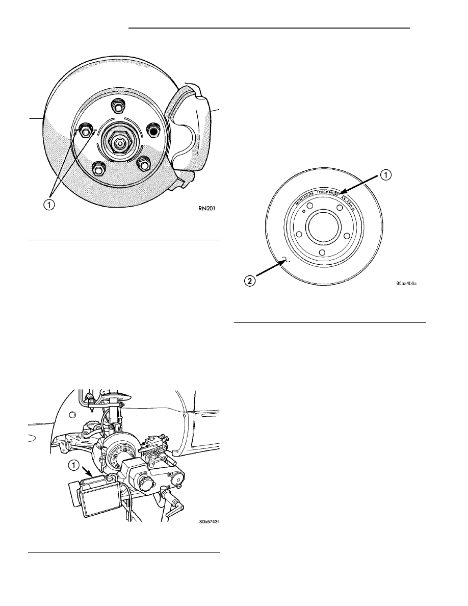
Fig. 125 Index Rotor And Wheel Stud

1 - CHALK MARK

Fig. 126 On-Car Brake Lathe

1 - ON-CAR BRAKE LATHE

Fig. 127 Minimum Brake Rotor Thickness (Typical)

1 - ROTOR MINIMUM THICKNESS MARKING
2 - ROTOR

5 - 64

BRAKES - BASE

PT

ROTOR (Continued)

REMOVAL

REMOVAL - FRONT BRAKE ROTOR

NOTE: Before proceeding, (Refer to 5 - BRAKES -
WARNING) (Refer to 5 - BRAKES - CAUTION).

(1) Raise the vehicle. (Refer to LUBRICATION &

MAINTENANCE/HOISTING - STANDARD PROCE-
DURE)

(2) Remove the front tire and wheel assembly.
(3) Slide the caliper outward in an effort to retract

the caliper piston into its bore.

(4) Remove the two bolts securing disc brake cali-

per adapter to the steering knuckle (Fig. 128).

(5) Remove the disc brake caliper and adapter

from the knuckle as an assembly. Hang the assembly
out of the way using wire or a bungee cord. Use care
not to overextend the brake hose when doing this.

(6) Remove the clips retaining the brake rotor to

the wheel studs.

(7) Remove the brake rotor.

REMOVAL - REAR BRAKE ROTOR

NOTE: Before proceeding, (Refer to 5 - BRAKES -
WARNING) (Refer to 5 - BRAKES - CAUTION).

(1) Raise the vehicle. (Refer to LUBRICATION &

MAINTENANCE/HOISTING - STANDARD PROCE-
DURE)

(2) Remove the rear tire and wheel assembly.
(3) Remove the rear disc brake caliper and shoes

from the brake rotor and store out of the way. (Refer
to

5

-

BRAKES/HYDRAULIC/MECHANICAL/

BRAKE PADS/SHOES - REMOVAL)

(4) Remove any clips retaining the brake rotor

(Fig. 21).

(5) Remove the brake rotor by pulling it straight

off the wheel mounting studs.

INSTALLATION

INSTALLATION - FRONT BRAKE ROTOR

CAUTION: When installing new brake components,
be sure to use correct parts. Parts designed for
BR4 Performance Brake System must not be mixed
with other brake systems. These parts, similar in
appearance, can be easily identified (Fig. 118).
(Refer to 5 - BRAKES/HYDRAULIC/MECHANICAL/
ROTOR - DESCRIPTION)

NOTE: Inspect disc brake shoes before installation.
(Refer to 5 - BRAKES/HYDRAULIC/MECHANICAL/
BRAKE PADS/SHOES - INSPECTION)

(1) Install the brake rotor over the studs on the

hub.

(2) Install the disc brake caliper and adapter

assembly over the brake rotor.

(3) Install the mounting bolts securing the caliper

adapter to the steering knuckle (Fig. 128). Tighten
the bolts to a torque of 104 N·m (77 ft. lbs.).

(4) Install the tire and wheel assembly. Tighten

the wheel mounting nuts to a torque of 135 N·m (100
ft. lbs.).

(5) Lower the vehicle.
(6) Pump the brake pedal several times before

moving the vehicle to set the shoes to the brake
rotor.

(7) Road test the vehicle and make several stops to

seat the brake shoes to the rotor.

INSTALLATION - REAR BRAKE ROTOR

CAUTION: When installing new brake components,
be sure to use correct parts. Parts designed for
BR4 Performance Brake System must not be mixed
with other brake systems. These parts, similar in
appearance, can be easily identified (Fig. 119).
(Refer to 5 - BRAKES/HYDRAULIC/MECHANICAL/
ROTOR - DESCRIPTION)

NOTE: Inspect disc brake shoes and parking brake
shoes before installation. (Refer to 5 - BRAKES/HY-
DRAULIC/MECHANICAL/BRAKE

PADS/SHOES

-

INSPECTION)

(1) Install the rear brake rotor over the wheel

mounting studs and onto the hub (Fig. 21).

Fig. 128 Caliper/Adapter Mounting

1 - STEERING KNUCKLE
2 - DISC BRAKE CALIPER
3 - DISC BRAKE CALIPER ADAPTER
4 - BRAKE ROTOR

PT

BRAKES - BASE

5 - 65

ROTOR (Continued)

(2) Install rear disc brake caliper and shoes. (Refer

to

5

-

BRAKES/HYDRAULIC/MECHANICAL/

BRAKE PADS/SHOES - INSTALLATION)

(3) Install the tire and wheel assembly. Tighten

the wheel mounting nuts to a torque of 135 N·m (100
ft. lbs.).

(4) Adjust the parking brake shoes as necessary.

(Refer to 5 - BRAKES/PARKING BRAKE/SHOES -
ADJUSTMENTS)

(5) Lower the vehicle.
(6) Pump the brake pedal before moving the vehi-

cle to set the brake shoes to the brake rotor.

SPECIFICATIONS

BRAKE ROTOR LIMITS/SPECIFICATIONS

NOTE: When refacing a rotor, the required TIR
(Total Indicator Reading) and thickness variation
limits MUST BE MAINTAINED.

BRB/BRK/BRT SALES CODE

Braking Rotor

Rotor Thickness

Minimum Rotor

Thickness

Rotor Thickness

Variation

Rotor Runout*

Front Rotor

22.91–23.10 mm

0.902–0.909 in.

21.40 mm

0.843 in.

0.010 mm

0.0004 in.

0.13 mm

0.005 in.

Rear Rotor

8.75–9.25 mm

0.344–0.364 in.

7.25 mm

0.285 in.

0.013 mm

0.0005 in.

0.13 mm

0.005 in.

* TIR Total Indicator Reading (Measured On Vehicle)

BR4 SALES CODE

Braking Rotor

Rotor Thickness

Minimum Rotor

Thickness

Rotor Thickness

Variation

Rotor Runout*

Front Rotor

27.91–28.10 mm

1.099–1.106 in.

26.40 mm

1.039 in.

0.010 mm

0.0004 in.

0.13 mm

0.005 in.

Rear Rotor

11.75–12.25 mm

0.463–0.482 in.

10.25 mm

0.404 in.

0.013 mm

0.0005 in.

0.13 mm

0.005 in.

* TIR Total Indicator Reading (Measured On Vehicle)

SUPPORT PLATE - DRUM
BRAKES

REMOVAL

NOTE: Before proceeding, (Refer to 5 - BRAKES -
WARNING) (Refer to 5 - BRAKES - CAUTION).

(1) Using a brake pedal holding tool as shown (Fig.

129), depress the brake pedal past its first one inch
of travel and hold it in this position. This will isolate
the master cylinder from the brake hydraulic system
and will not allow the brake fluid to drain out of the
master cylinder reservoir.

(2) Raise the vehicle. (Refer to LUBRICATION &

MAINTENANCE/HOISTING - STANDARD PROCE-
DURE)

(3) Remove the rear tire and wheel assembly.

(4) If equipped with ABS, remove the bolt attach-

ing the wheel speed sensor to the support plate (Fig.
130), then carefully remove the sensor head.

Fig. 129 Brake Pedal Holding Tool

5 - 66

BRAKES - BASE

PT

ROTOR (Continued)

(5) Disconnect the rear brake tube from the wheel

cylinder (Fig. 131).

(6) Remove the rear brake drum (Fig. 132). (Refer

to 5 - BRAKES/HYDRAULIC/MECHANICAL/DRUM
- REMOVAL)

(7) Remove the dust cap from the rear hub and

bearing (Fig. 132).

(8) Remove the nut holding the rear hub and bear-

ing to the spindle (Fig. 132). Remove the hub and
bearing from the spindle.

(9) Remove the rear brake shoes from the brake

support plate. (Refer to 5 - BRAKES/HYDRAULIC/
MECHANICAL/BRAKE PADS/SHOES - REMOVAL)

(10) If not previously removed, remove the parking

brake actuator lever from the parking brake cable.

(11) Position a

1

2

inch wrench over the retainer

fingers on the end of the parking brake cable (Fig.
133). Compress the cable housing retaining fingers
with the wrench, then pull the cable housing out of
the support plate. Remove the wrench as the parking
brake cable retainer is freed from the mounting hole
in the brake support plate.

Fig. 130 Right Rear Wheel Speed Sensor

1 - SHOCK ABSORBER
2 - RIGHT REAR WHEEL SPEED SENSOR

Fig. 131 Wheel Cylinder Mounting

1 - BRAKE SUPPORT PLATE
2 - WHEEL CYLINDER MOUNTING BOLTS
3 - REAR BRAKE TUBE
4 - WHEEL CYLINDER ASSEMBLY

Fig. 132 Drum Brakes

1 - DUST CAP
2 - NUT
3 - DRUM
4 - HUB AND BEARING
5 - WHEEL CYLINDER
6 - SUPPORT PLATE
7 - BRAKE SHOES

Fig. 133 Removing Park Brake Cable From Support

Plate

1 - WRENCH
2 - CABLE HOUSING RETAINER
3 - PARK BRAKE CABLE
4 - SUPPORT PLATE

PT

BRAKES - BASE

5 - 67

SUPPORT PLATE - DRUM BRAKES (Continued)


Content   ..  426  427  428  429   ..