Chrysler PT Cruiser. Manual - part 406


  Index      Chrysler     Chrysler PT Cruiser - service repair manual 2005 year


Search            


Content   ..  404  405  406  407   ..


Chrysler PT Cruiser. Manual - part 406


(6) Tighten the four mounting bolts to a torque of

95 N·m (70 ft. lbs.).

(7) Reassemble the rear brake following the Spin-

dle Installation procedure found in Rear Suspension.
(Refer

to

2

-

SUSPENSION/REAR/SPINDLE

-

INSTALLATION)

(8) Reinstall the tire and wheel assembly. Tighten

the wheel mounting nuts to a torque of 135 N·m (100
ft. lbs.).

(9) Lower the vehicle.
(10) Once rear camber and toe have been set to

specifications, check and adjust the front wheel align-
ment as necessary. Refer to FRONT CAMBER AND
CASTER and FRONT TOE within this wheel align-
ment service procedure.

FRONT CAMBER AND CASTER

Front camber and caster settings on this vehicle

are determined at the time the vehicle is designed,
by the location of the vehicle’s suspension compo-
nents. This is referred to as Net Build. The result is
no required adjustment of camber and caster after
the vehicle is built or when servicing the suspension
components. Thus, when performing a wheel align-
ment, caster and camber are not normally considered
adjustable angles. Camber and caster should be
checked to ensure they meet vehicle specifications.
(Refer to 2 - SUSPENSION/WHEEL ALIGNMENT -
SPECIFICATIONS)

If front camber is found not to meet alignment

specifications, it can be adjusted using an available
camber adjustment bolt package. Before installing a
camber adjustment bolt package on a vehicle found
to be outside the specifications, inspect the suspen-
sion components for any signs of damage or bending.

No adjustment can be made to the caster setting

on this vehicle. If the vehicle’s caster is not within
alignment specifications, check for damaged suspen-
sion components or body parts.

CAUTION: Do not attempt to adjust the vehicles
wheel alignment by heating or bending any of the
suspension components.

CAMBER ADJUSTMENT BOLT PACKAGE INSTALLATION

The camber adjustment bolt package contains new

bolts and nuts for attaching the strut clevis bracket
to the steering knuckle. The bolts contained in the
package are slightly undersize allowing for move-
ment between the strut clevis bracket and the steer-
ing knuckle. The movement allowed by the undersize
bolts provide approximately two degrees of camber
adjustment per side of the vehicle. To install and
adjust the camber adjustment bolt package, follow
the procedure below.

(1) Raise the vehicle until its tires are not support-

ing the weight of the vehicle.

CAUTION: The knuckle to strut assembly attaching
bolt shanks are serrated and must not be turned
during removal. Remove the nuts while holding the
bolts stationary.

(2) Remove the original upper bolt attaching the

strut clevis bracket to the knuckle (Fig. 7).

(3) Install a bolt from the adjustment package into

the hole where the original bolt was removed. Install
the bolt from the rear.

(4) Install a nut provided in adjustment package

on the replacement bolt. Tighten the nut until it’s
snug, but still allowing the knuckle to slide in the
clevis bracket.

(5) Remove the original lower bolt.
(6) Install a bolt from the adjustment package into

the bottom hole of the strut clevis bracket. Install the
bolt from the rear.

(7) Install a nut provided in adjustment package on

the replacement bolt. Tighten the nut until it’s snug.

(8) Reinstall the tire and wheel assembly. Tighten

the wheel mounting nuts to a torque of 135 N·m (100
ft. lbs.)

(9) Perform the above procedure to opposite strut

as required.

(10) Lower the vehicle and jounce the front and

rear of the vehicle.

(11) Adjust the front camber to the preferred set-

ting by pushing or pulling on the top of the tire.
When camber is set to specifications, tighten the

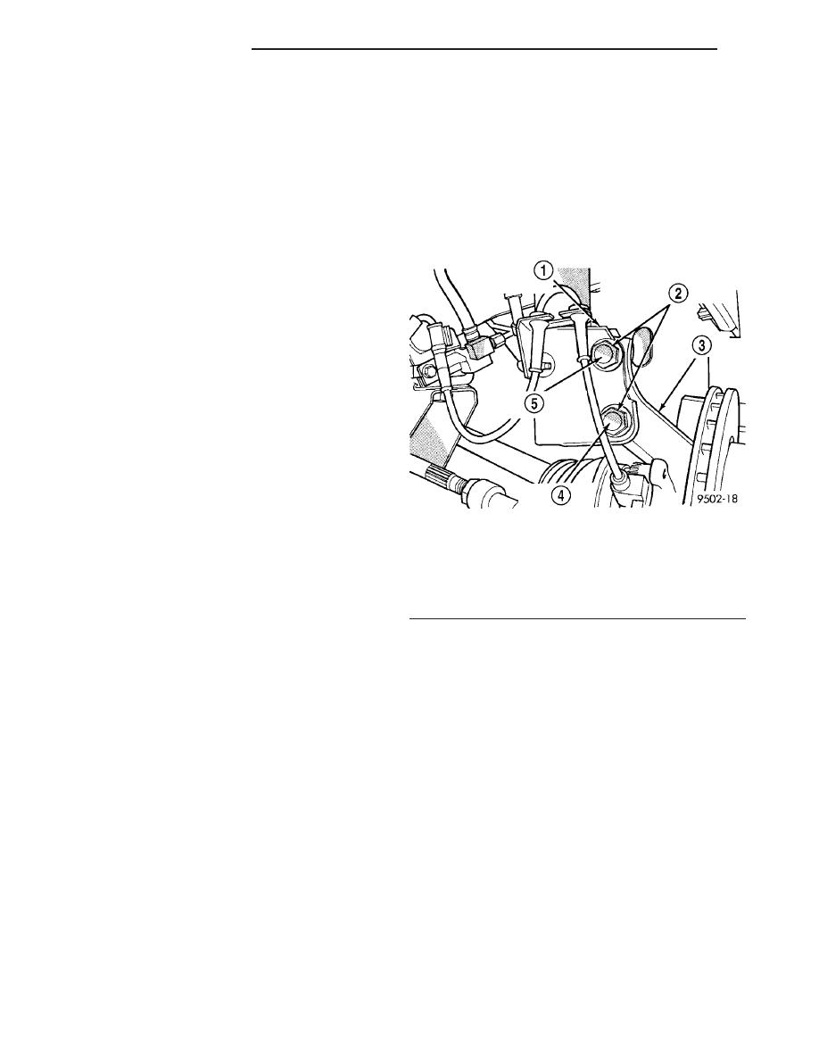
Fig. 7 Front Strut Clevis Bracket Attaching Bolts

1 - STRUT CLEVIS BRACKET
2 - STRUT CLEVIS BRACKET TO STEERING KNUCKLE
ATTACHING BOLTS
3 - STEERING KNUCKLE
4 - LOOSEN THIS BOLT
5 - REMOVE AND REPLACE THIS BOLT

2 - 60

WHEEL ALIGNMENT

PT

WHEEL ALIGNMENT (Continued)

upper and lower strut clevis bracket bolts. Again
jounce the front and rear of the vehicle, then verify
the camber settings.

(12) Torque front strut clevis bracket-to-steering

knuckle attaching bolts to a torque of 163 N·m (120
ft. lbs.).

(13) Once camber is within specifications, adjust

toe to meet the preferred specification setting. Refer
to FRONT TOE within this wheel alignment service
procedure.

FRONT TOE

(1) Center the steering wheel and lock it in place

using a steering wheel clamp.

CAUTION: Do not twist the inner tie rod-to-steering
gear rubber boots while turning the inner tie rod
during the front toe adjustment.

(2) Loosen the tie rod adjusting jam nuts (Fig. 8).

Grasp each inner tie rod at its splines and rotate it
one way or the other until the front wheel toe is set
to the preferred specification. (Refer to 2 - SUSPEN-
SION/WHEEL ALIGNMENT - SPECIFICATIONS)

(3) Tighten tie rod adjusting jam nuts to a torque

of 75 N·m (55 ft. lbs.).

(4) Make sure the inner tie rod-to-steering gear

rubber boots are not twisted. If twisted, loosen the
boot clamp at the inner tie rod and move the boot as
necessary.

(5) Remove steering wheel clamp.
(6) Remove the alignment equipment.
(7) Road test the vehicle to verify the steering

wheel is straight and the vehicle does not pull or
wander.

SPECIFICATIONS

WHEEL ALIGNMENT

NOTE: All specifications are given in degrees.

NOTE: All wheel alignments are to be set with the
vehicle at curb height. (Refer to 2 - SUSPENSION/
WHEEL ALIGNMENT - STANDARD PROCEDURE)

FRONT WHEEL ALIGNMENT

PREFERRED SETTING

ACCEPTABLE RANGE

CAMBER

0.00°

-0.40° to +0.40°

Cross Camber (Maximum Side-To-
Side Difference)

0.00°

0.50

CASTER

+2.45°

+1.45° to +3.45°

Cross Caster (Maximum Side-To-Side
Difference)

0.00°

1.00°

TOTAL TOE*

+0.10°

0.00° to +0.20°

REAR WHEEL ALIGNMENT

PREFERRED SETTING

ACCEPTABLE RANGE

CAMBER

0.00°

-0.25° to +0.25°

TOTAL TOE*

+0.20°

+0.00° to +0.40°

THRUST ANGLE

0.00°

-0.30° to +0.30°

Note:

* TOTAL TOE is the sum of both the left and right wheel toe settings. TOTAL TOE must be equally split between
each front wheel to ensure the steering wheel is centered after setting toe. Positive toe (+) is toe-in and negative
toe (

2

) is Toe-out.

Fig. 8 Jam Nut Locations (Typical)

1 - OUTER TIE ROD
2 - INNER TIE ROD SPLINES
3 - JAM NUT

PT

WHEEL ALIGNMENT

2 - 61

WHEEL ALIGNMENT (Continued)

DIFFERENTIAL & DRIVELINE

HALF SHAFT

TABLE OF CONTENTS

page

page

HALF SHAFT

DESCRIPTION

. . . . . . . . . . . . . . . . . . . . . . . . . . 1

OPERATION

. . . . . . . . . . . . . . . . . . . . . . . . . . . . 3

DIAGNOSIS AND TESTING - HALFSHAFT

DIAGNOSIS

. . . . . . . . . . . . . . . . . . . . . . . . . . . 3

REMOVAL

REMOVAL—EXCEPT DIESEL AND TURBO

MODELS . . . . . . . . . . . . . . . . . . . . . . . . . . . . . 4

REMOVAL—DIESEL AND TURBO MODELS

. . 6

INSTALLATION

INSTALLATION—EXCEPT DIESEL AND

TURBO MODELS . . . . . . . . . . . . . . . . . . . . . . . 9

INSTALLATION—DIESEL AND TURBO

MODELS . . . . . . . . . . . . . . . . . . . . . . . . . . . . 12

SPECIFICATIONS - TORQUE

. . . . . . . . . . . . . . 14

SPECIAL TOOLS

HALFSHAFT

. . . . . . . . . . . . . . . . . . . . . . . . . 14

CV BOOT - INNER

REMOVAL

. . . . . . . . . . . . . . . . . . . . . . . . . . . . . 14

INSTALLATION

. . . . . . . . . . . . . . . . . . . . . . . . . 15

CV BOOT - OUTER

REMOVAL

. . . . . . . . . . . . . . . . . . . . . . . . . . . . . 20

INSTALLATION

. . . . . . . . . . . . . . . . . . . . . . . . . 21

HALF SHAFT

DESCRIPTION

All Models Except Diesel and Turbo

1.6/2.4L naturally aspirated models equipped with

either an automatic or manual transmission use an
unequal-length halfshaft system. The system incorpo-
rates two halfshaft assemblies (left and right) that
consist of an inner and outer constant velocity (CV)
joint and a solid interconnecting shaft (Fig. 1). The

right halfshaft is longer than the left due to trans-
axle packaging and powertrain design.

Halfshafts used on both the right and left sides of

the vehicle use a tuned rubber damper weight
mounted to the interconnecting shaft (Fig. 1). The
damper weight applications vary by which side of the
vehicle the halfshaft is located on and the transmis-
sion application of the vehicle. When replacing a
halfshaft, be sure the replacement halfshaft has the
same damper weight as the original.

PT

DIFFERENTIAL & DRIVELINE

3 - 1


Content   ..  404  405  406  407   ..