Chrysler PT Cruiser. Manual - part 382


  Index      Chrysler     Chrysler PT Cruiser - service repair manual 2005 year


Search            


Content   ..  380  381  382  383   ..


Chrysler PT Cruiser. Manual - part 382


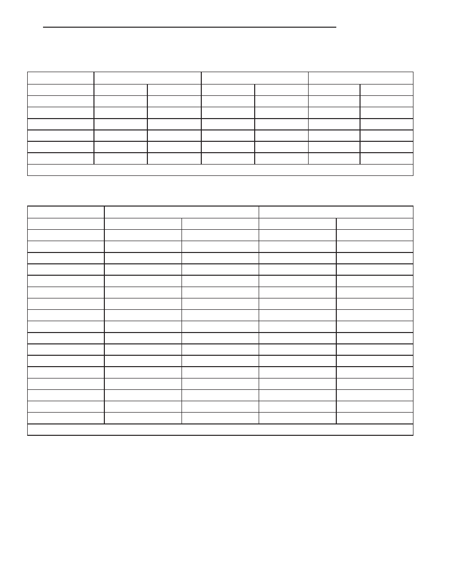
BOLT MARKINGS AND TORQUES - METRIC

Bolt Markings

8.8/8.9

10.9

12.9

Bolt Dia.

N·m

Ft. Lbs.

N·m

Ft. Lbs.

N·m

Ft. Lbs.

6

12

105*

14

120*

16

12

8

25

250*

32

23

38

28

10

54

40

60

45

74

55

12

95

70

108

80

135

100

14

155

115

175

130

216

160

16

243

180

324

210

324

240

* Inch Lbs.

BOLT MARKINGS AND TORQUES - U. S. CUSTOMARY

Bolt Markings

Grade 5

Grade 8

Bolt Dia.

N·m

Ft. Lbs

N·m

Ft. Lbs

1/4 - 20

10

95*

14

125*

1/4 - 28

10

95*

17

150*

5/16 - 18

22

200*

30

270*

5/16 - 24

26

240*

33

300*

3/8 - 16

40

30

55

40

3/8 - 24

47

35

60

45

7/16 - 14

68

50

88

65

7/16 - 20

74

55

95

70

1/2 - 13

101

75

135

100

1/2 -20

115

85

150

110

9/16 - 12

135

105

182

135

9/16 - 18

155

115

202

150

5/8 - 11

202

150

263

195

5/8 - 18

215

160

284

210

3/4 - 10

230

170

297

220

3/4 - 16

236

175

304

225

7/8 - 14

405

300

540

400

* Inch Lbs.

PT

INTRODUCTION

3

FASTENER IDENTIFICATION (Continued)

FASTENER STRENGTH

4

INTRODUCTION

PT

FASTENER IDENTIFICATION (Continued)

FASTENER USAGE

DESCRIPTION

FASTENER USAGE

WARNING: USE OF AN INCORRECT FASTENER
MAY RESULT IN COMPONENT DAMAGE OR PER-
SONAL INJURY.

Fasteners and torque specifications references in

this Service Manual are identified in metric and SAE
format.

During any maintenance or repair procedures, it is

important to salvage all fasteners (nuts, bolts, etc.)
for reassembly. If the fastener is not salvageable, a
fastener of equivalent specification must be used.

THREADED HOLE REPAIR

Most stripped threaded holes can be repaired using

a Helicoil

t. Follow the vehicle or Helicoilt recommen-

dations for application and repair procedures.

INTERNATIONAL SYMBOLS

DESCRIPTION

The graphic symbols illustrated in the following

International Control and Display Symbols Chart are
used to identify various instrument controls. The
symbols correspond to the controls and displays that
are located on the instrument panel.

METRIC SYSTEM

DESCRIPTION

The metric system is based on quantities of one,

ten, one hundred, one thousand and one million.

The following chart will assist in converting metric

units to equivalent English and SAE units, or vise
versa.

INTERNATIONAL CONTROL AND DISPLAY SYMBOLS

1

High Beam

13

Rear Window Washer

2

Fog Lamps

14

Fuel

3

Headlamp, Parking Lamps, Panel Lamps

15

Engine Coolant Temperature

4

Turn Warning

16

Battery Charging Condition

5

Hazard Warning

17

Engine Oil

6

Windshield Washer

18

Seat Belt

7

Windshield Wiper

19

Brake Failure

8

Windshield Wiper and Washer

20

Parking Brake

9

Wind screen Demisting and Defrosting

21

Front Hood

10

Ventilating Fan

22

Rear hood (Decklid)

11

Rear Window Defogger

23

Horn

12

Rear Window Wiper

24

Lighter

PT

INTRODUCTION

5

METRIC CONVERSION CHART

6

INTRODUCTION

PT

METRIC SYSTEM (Continued)


Content   ..  380  381  382  383   ..