Chrysler PT Cruiser. Manual - part 216


  Index      Chrysler     Chrysler PT Cruiser - service repair manual 2005 year


Search            


Content   ..  214  215  216  217   ..


Chrysler PT Cruiser. Manual - part 216


FUEL

SYSTEM

-

STANDARD

PROCEDURE).

Replace any damaged, restricted or leaking high-
pressure fuel lines with the correct replacement line.

CAUTION: The high-pressure fuel lines cannot con-
tact each other or other components. Do not
attempt to weld high-pressure fuel lines or to repair
lines that are damaged. Only use the recommended
lines when replacement of high-pressure fuel line is
necessary.

DIAGNOSIS AND TESTING - AIR IN FUEL
SYSTEM

Air will enter the fuel system whenever fuel supply

lines, separator filters, injection pump, high-pressure
lines or injectors are removed or disconnected. Air
trapped in the fuel system can result in hard start-
ing, a rough running engine, engine misfire, low
power, excessive smoke and fuel knock.

Inspect the fuel system from the fuel tank to the

injectors for loose connections (Refer to 14 - FUEL
SYSTEM - WARNING). Leaking fuel is an indicator
of loose connections or defective seals. Air can also
enter the fuel system between the fuel tank and the
fuel pump. Inspect the fuel tank module and fuel
lines for damage that might allow air into the sys-
tem.

With the DRBIII

t connected to the vehicle, select

Engine and the select Sensor Display. Page down to
view Fuel Pressure Set Point and Actual Fuel Pres-

sure. Start the engine and observe the Fuel Pressure
Set Point and the Actual Fuel Pressure. If the Actual
Fuel Pressure Oscillates above and below the Fuel
Pressure Set Point in a regular cycle, inspect the fuel
system for air intrusion.

If the Actual Fuel Pressure gradually drops below

the Fuel Pressure Set Point then spikes well above
the Fuel Pressure Set Point, replace the fuel pres-
sure control valve (Refer to 14 - FUEL SYSTEM/
FUEL INJECTION/FUEL PRESSURE SOLENOID -
REMOVAL), and recheck.

DIAGNOSIS AND TESTING - INJECTOR LEAK
QUANTITY

WARNING: REVIEW THE HIGH PRESSURE FUEL
SYSTEM WARNING BEFORE BEGINNING SERVICE
(Refer to 14 - FUEL SYSTEM - WARNING).

NOTE: If an injector is found to be out of specifica-
tion, repeat this test procedure after the injector
replacement. Hydraulic flow will take the path of
least resistance and multiple failures may be identi-
fied.

Perform this test with the engine at operating tem-

perature. This test will assist in determining a defec-
tive or internally leaking injector(s) is present by
measuring the amount of fuel return.

(1) Turn the ignition off.
(2) Remove the engine cover (Refer to 9 - ENGINE

- REMOVAL).

(3) Disconnect the fuel return hoses at the top of

the injectors.

(4) Disconnect and block off the oil return line at

the banjo bolt fitting of the fuel rail.

(5) Disconnect the fuel rail solenoid.
(6) Install the test vials onto the injectors and

secure with the return hose clips (Fig. 2).

(7) Crank the engine for ten seconds while moni-

toring each inner test vial.

After ten seconds, a maximum of two graduation

lines may be reached. If the level has exceeded the
two graduation line, replace that effected cylinder’s
injector, clear the memory using the scan tool, empty
the test vials, and retest. If the level did not pass the
two graduation line limit, continue to the next step.

(8) Turn the ignition off. Leave the emptied test

vials in place. Reconnect the fuel pressure solenoid.
Disconnect the cam position sensor, crank the engine
for ten seconds.

After ten seconds, a maximum of four graduation

lines of the inner test vial may be reached. If the
level has exceeded the four graduation line, replace
that effected cylinder’s injector, clear the memory
using the scan tool, empty the test vials, and retest.

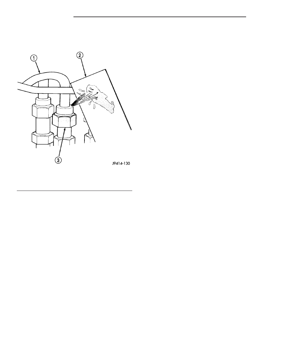
Fig. 1 Typical Test for Leaks with Cardboard

1 - HIGH-PRESSURE LINE
2 - CARDBOARD
3 - FITTING

14 - 2

FUEL SYSTEM

PT

FUEL SYSTEM - 2.2L DIESEL (Continued)

If the level did not pass the four graduation line
limit, continue with the diagnostic manual.

STANDARD PROCEDURE

STANDARD PROCEDURES - CLEANING FUEL
SYSTEM COMPONENTS

CAUTION: Cleanliness cannot be overemphasized
when handling or replacing diesel fuel system com-
ponents. This especially includes the fuel injectors,
high-pressure fuel lines, fuel rail, and fuel injection
pump. Very tight tolerances are used with these
parts. Dirt contamination could cause rapid part
wear and possible plugging of fuel injector nozzle
tip holes. This in turn could lead to possible engine
misfire. Always wash/clean any fuel system compo-
nent thoroughly before disassembly and then air
dry. DO NOT wire brush injector nozzles when
cleaning. Cap or cover any open part after disas-
sembly. Before assembly, examine each part for
dirt, grease or other contaminants and clean if nec-
essary. When installing new parts, lubricate them
with clean engine oil or clean diesel fuel only.

STANDARD PROCEDURES - DRAINING WATER
FROM FUEL FILTER

Connect a hose to the Water in Fuel (WIF) drain

and place it in a clearly marked and suitable con-
tainer. Open the WIF drain by turning counterclock-
wise (Fig. 3). Turn the ignition key on for 20 seconds
(Refer to low pressure fuel pump operation). Repeat

the procedure until all water is removed, close the
drain and remove the hose.

STANDARD PROCEDURE - LOW PRESSURE
FUEL PUMP TEST

NOTE: Assure fuel tank quantity and proper fuel
gauge operation. Assure that the fuel pump fuse or
relay is not open. Capture any fuel spillage and
store in appropriately marked containers.

NOTE: When the ignition switch is turned to the On
position the fuel pump will begin to run for 20–30
seconds and then it stops.

The low pressure pump draws fuel out of the fuel

tank module mixing bowl and pushes the fuel
towards the fuel filter. If the pressure reading is
below specification, look for damaged or leaking fuel
lines or a restricted fuel filter. If no problem is found
with the fuel system replace the low pressure fuel
pump.

(1) Disconnect the negative battery cable.
(2) Connect a fuel gauge to the low pressure fuel

supply to the high pressure pump (Fig. 4).

(3) Connect negative battery cable.
(4) Turn the ignition to the On position and

observe the fuel gauge reading (Fig. 5).

Fig. 2 Special Tool # 9545

1 - SPECIAL TOOL #9545

Fig. 3 WATER IN FUEL SENSOR

1 - WIF SENSOR
2 - WIF DRAIN
3 - FUEL FILTER
4 - FUEL SUPPLY FROM TANK
5 - FUEL SUPPLY TO HIGH PRESSURE PUMP

PT

FUEL SYSTEM

14 - 3

FUEL SYSTEM - 2.2L DIESEL (Continued)

If the fuel pressure is within specification, recon-

nect the fuel line to the high pressure pump and con-
tinue with the diagnostics. If the fuel pressure is
below specification, disconnect the low pressure fuel
pump input line to the fuel filter and re-test follow-
ing the steps above (Fig. 6).

If the fuel pressure is below specification, replace

the fuel pump. If the fuel pressure is equal to the
specification, replace the fuel filter.

FUEL PRESSURE SPECIFICATIONS

SUCTION PRESSURE

7.25 PSI (0.5 bar)

DELIVERY PRESSURE

65 PSI (4.5 bar)

MAXIMUM FUEL
DELIVERY

53 gallons/hour(200
liters/hour)

Fig. 4 FUEL GAUGE CONNECT AT HIGH PRESSURE

PUMP

1 - FUEL SUPPLY FITTING
2 - ADAPTOR
3 - FUEL GAUGE HOSE
4 - HIGH PRESSURE PUMP
5 - FUEL RETURN FITTING

Fig. 5 FUEL PRESSURE TEST AT HIGH PRESSURE

PUMP

Fig. 6 FUEL PRESSURE TEST AT FILTER

1 - FUEL SUPPLY FROM FUEL TANK
2 - FUEL FILTER ASSEMBLY

14 - 4

FUEL SYSTEM

PT

FUEL SYSTEM - 2.2L DIESEL (Continued)

SPECIAL TOOLS

#8933 CRANKSHAFT LOCK

#8937 SLIDE HAMMER

#8938 EXTRACTION CLAW

PT

FUEL SYSTEM

14 - 5

FUEL SYSTEM - 2.2L DIESEL (Continued)


Content   ..  214  215  216  217   ..