Chrysler Pacifica. Manual - part 889
Refer to the appropriate wiring information for
diagnosis and testing of the micro-relay and for com-
plete HVAC wiring diagrams.
REMOVAL
(1) Disconnect and isolate the negative battery
cable.
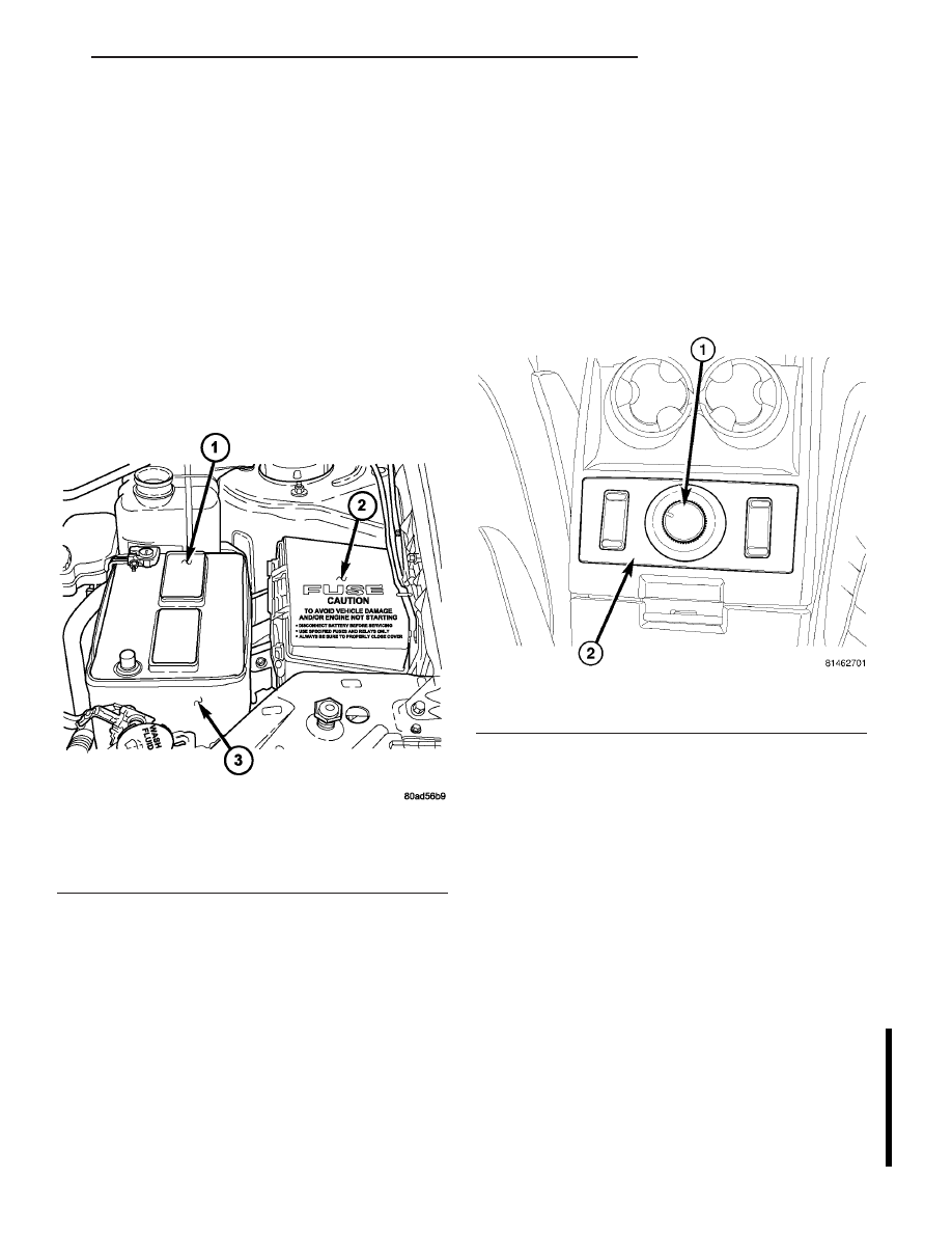
(2) Remove the cover from the integrated power
module (IPM) located in the engine compartment
(Fig. 2).
NOTE: Refer to the fuse and relay map on the IPM
cover for rear blower motor relay location.
(3) Remove the rear blower motor relay from the
IPM.
INSTALLATION
NOTE: Refer to the fuse and relay map on the cover
of the integrated power module (IPM) for rear
blower motor relay location.
(1) Position the rear blower motor relay to the
proper receptacle in the IPM.
(2) Align the rear blower motor relay terminals
with the terminal cavities in the IPM receptacle and
push down firmly on the relay until the terminals
are fully seated.
(3) Install the cover onto the IPM.
(4) Reconnect the negative battery cable.
BLOWER MOTOR SWITCH
DESCRIPTION
The rear blower motor is controlled by a rotary-
type blower motor switch, mounted in the rear center
console (Fig. 3). The rear blower motor switch allows
the selection of rear blower motor speeds, Auto and
an Off position when the front A/C-heater control is
set to the Rear position, otherwise the front A/C-
heater control operates both the front and rear
blower motors.
OPERATION
When the front A/C-heater control display for the
automatic temperature control (ATC) heating-A/C
system reads REAR AUTO or when the rear blower
fan is off, the switch located in the center console
between the second row seats is not functional. When
the front A/C-heater control display reads REAR,
only the rear seat occupants control the rear blower
fan speed from the rear switch. When in the Rear
mode, the rear occupants can set the rear switch to
any fan speed including OFF or AUTO. While in the
Auto position, the rear fan speed will be automati-
cally controlled. Refer to Body Diagnostic Procedures
for further diagnostic information.
REMOVAL
NOTE: The rear blower motor switch and the rear
floor console switch bezel are serviced only as an
assembly.
(1) Disconnect and isolate the negative battery
cable.
Fig. 2 Integrated Power Module (IPM)
1 - BATTERY
2 - INTEGRATED POWER MODULE (IPM)
3 - BATTERY THERMAL GUARD
Fig. 3 Rear Blower Motor Switch
1 - REAR BLOWER MOTOR SWITCH
2 - REAR CONTROL PANEL
CS
CONTROLS - REAR
24 - 33
BLOWER MOTOR RELAY (Continued)
2005 CS Service Manual
Publication No. 81-270-05050
05CS24-33
July, 2004