Chrysler Pacifica. Manual - part 820
INSTRUMENT PANEL
TABLE OF CONTENTS
page
page
CLUSTER BEZEL
. . . . . . . . . . . . . . . . . . . . . . . . . . . . . 75
. . . . . . . . . . . . . . . . . . . . . . . . . 75
GLOVE BOX
. . . . . . . . . . . . . . . . . . . . . . . . . . . . . 76
. . . . . . . . . . . . . . . . . . . . . . . . . 76
GLOVE BOX LATCH
. . . . . . . . . . . . . . . . . . . . . . . . . . . . . 76
. . . . . . . . . . . . . . . . . . . . . . . . . 76
GLOVE BOX LATCH STRIKER
. . . . . . . . . . . . . . . . . . . . . . . . . . . . . 76
. . . . . . . . . . . . . . . . . . . . . . . . . 76
INSTRUMENT PANEL ASSEMBLY
. . . . . . . . . . . . . . . . . . . . . . . . . . . . . 77
. . . . . . . . . . . . . . . . . . . . . . . . . 81
INSTRUMENT PANEL CENTER BEZEL
. . . . . . . . . . . . . . . . . . . . . . . . . . . . . 82
. . . . . . . . . . . . . . . . . . . . . . . . . 82
INSTRUMENT PANEL FLOOR BRACKET
. . . . . . . . . . . . . . . . . . . . . . . . . . . . . 82
. . . . . . . . . . . . . . . . . . . . . . . . . 83
INSTRUMENT PANEL END CAP
. . . . . . . . . . . . . . . . . . . . . . . . . . . . . 83
. . . . . . . . . . . . . . . . . . . . . . . . . 83
INSTRUMENT PANEL TOP COVER
. . . . . . . . . . . . . . . . . . . . . . . . . . . . . 84
. . . . . . . . . . . . . . . . . . . . . . . . . 84
STEERING COLUMN OPENING COVER
. . . . . . . . . . . . . . . . . . . . . . . . . . . . . 85
. . . . . . . . . . . . . . . . . . . . . . . . . 85
CLUSTER BEZEL
REMOVAL
(1) Open hood, disconnect and isolate the battery
negative cable.
(2) Remove the steering opening cover two retain-
ing screws and cover.
(3) Remove the knee blocker airbag (Refer to 8 -
ELECTRICAL/RESTRAINTS/KNEE BLOCKER AIR-
BAG - REMOVAL).
(4) Unsnap the left end cover and remove.
(5) Remove the two screws to the left lower instru-
ment panel trim plate.
(6) Remove the instrument panel center bezel
(Refer to 23 - BODY/INSTRUMENT PANEL/IN-
STRUMENT PANEL CENTER BEZEL - REMOVAL).
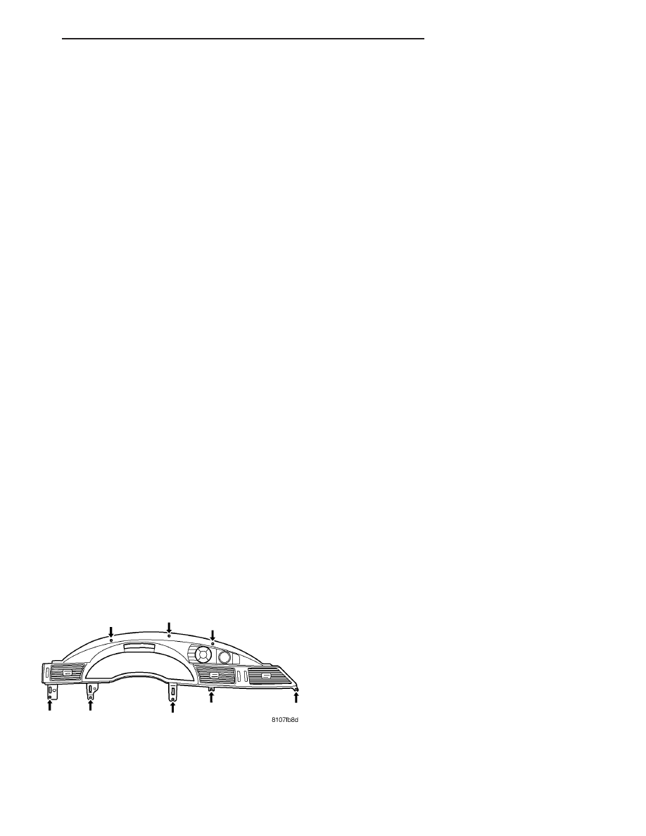
(7) Remove the eight retaining screws to the clus-
ter bezel (Fig. 1).
(8) Using a trim stick or equivalent, gently pry out
on cluster bezel around edges and remove from
instrument panel (Fig. 2).
(9) Disconnect
the
electrical
connector
to
the
instrument panel switch pod (EVIC, NAV, Clock, and
Hazard Switch).
INSTALLATION
(1) Connect the electrical connector to the instru-
ment panel switch pod (EVIC, NAV, Clock, and Haz-
ard Switch).
(2) Position the cluster bezel over retaining slots
and firmly snap into place (Fig. 2).
(3) Install the eight retaining screws to the cluster
bezel (Fig. 1).
(4) Position the left side instrument panel center
stack trim from panel over retaining slots and firmly
snap into place.
(5) Install the instrument panel center bezel (Refer
to 23 - BODY/INSTRUMENT PANEL/INSTRUMENT
PANEL CENTER BEZEL - INSTALLATION).
(6) Position the left lower instrument panel trim
plate over the retaining slots and firmly snap into
place. Install the two screws.
(7) Position the left end cover over the retaining
slots and firmly snap into place.
(8) Install the knee blocker airbag (Refer to 8 -
ELECTRICAL/RESTRAINTS/KNEE BLOCKER AIR-
BAG - INSTALLATION).
(9) Position the steering opening cover over retain-
ing and firmly snap into place. Install the two retain-
ing screws.
Fig. 1 CLUSTER BEZEL MOUNTING SCREW
LOCATION
CS
INSTRUMENT PANEL
23 - 75