Chrysler Pacifica. Manual - part 768
(14) Install cradle and fixture into position under
vehicle.
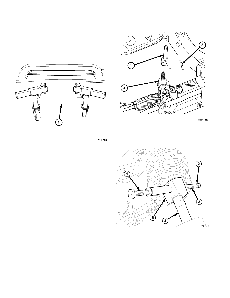
(15) Slowly lower vehicle (Fig. 193). Have helper
guide power steering and brake hydraulic lines into
position, while aligning cradle to body. While lower-
ing vehicle, align engine front and rear mount studs
to their respective thru-holes in cradle.
(16) Aligning index/scribe mark placed upon disas-
sembly, Install four (4) cradle-to-body bolts and
torque to 162 N·m (120 ft. lbs.).
(17) Verify that power steering and brake hydrau-
lic lines can be properly routed and installed.
(18) Remove overhead powertrain support fixture
from engine compartment:
(a) Remove rear support/lift bracket and connect
coolant temperature sensor.
(b) Remove front support/lift bracket. Install and
torque engine oil dipstick fastener.
(19) Raise vehicle on hoist and remove driveline
support table.
(20) Install and torque engine front and rear
mount-to-cradle nuts to 54 N·m (40 ft. lbs.).
(21) Using Tool 6831A, install steering shaft-to-
gear coupler (Fig. 194) (Fig. 195)
Fig. 193 Driveline Support Table in Position
1 - DRIVELINE SUPPORT TABLE 8874
Fig. 194 Intermediate Shaft Extension at Gear
1 - INTERMEDIATE SHAFT EXTENSION
2 - ROLL PIN
3 - STEERING GEAR
Fig. 195 Roll Pin Installation
1 - INSTALLER 6831A
2 - KNURLED NUT
3 - ROLL PIN
4 - STEERING GEAR SHAFT
5 - INTERMEDIATE SHAFT EXTENSION
CS
41AE/TE AUTOMATIC TRANSAXLE
21 - 67
41AE/TE AUTOMATIC TRANSAXLE (Continued)