Chrysler Pacifica. Manual - part 739
3.8L - UPPER O2 SENSOR
The engines uses two heated oxygen sensors.
CAUTION: When disconnecting the sensor electrical
connector, do not pull directly on wire going into
sensor.
(1) Disconnect negative battery cable.
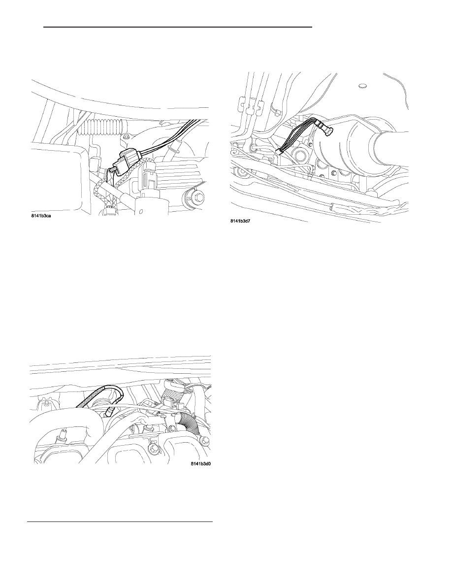
(2) Disconnect the upper O2 sensor connector (Fig.
64).
(3) Use a socket such as Snap-On YA8875 or a
crow foot wrench to remove oxygen sensor (Fig. 65).
3.8L - LOWER O2 SENSOR
The engines uses two heated oxygen sensors.
CAUTION: When disconnecting the sensor electrical
connector, do not pull directly on wire going into
sensor.
(1) Disconnect negative battery cable.
(2) Raise and support vehicle.
(3) Disconnect the electrical connector.
(4) Use a socket such as Snap-On YA8875 or a
crow foot wrench to remove oxygen sensor (Fig. 66).
INSTALLATION
3.5L
NOTE: When replacing an O2 Sensor, the PCM RAM
memory must be cleared, either by disconnecting
the PCM C-1 connector or momentarily disconnect-
ing the Battery negative terminal. The NGC learns
the characteristics of each O2 heater element and
these old values should be cleared when installing
a new O2 sensor. The customer may experience
driveability issues if this is not performed.
(1) After removing the sensor, the threads must be
cleaned with an 18 mm X 1.5 + 6E tap. If reusing the
original sensor, coat the sensor threads with an anti-
seize compound such as Loctite 771- 64 or equivalent.
New sensors have compound on the threads and do
not require an additional coating. Tighten the sensor
to 28 N·m (20 ft. lbs.) torque.
(2) Connect the heated oxygen sensor electrical
connector.
Fig. 64 O2 SENSOR CONNECTOR
Fig. 65 UPSTREAM O2 SENSOR
1 - Item_1xftjhxfdj
2 - Item _2tjsryjy
Fig. 66 LOWER O2 LOCATION
CS
FUEL INJECTION
14 - 47
O2 SENSOR (Continued)