Chrysler Pacifica. Manual - part 716
 

  Index      Chrysler     Chrysler Pacifica - service repair manual 2005 year


Search            


Content   ..  714  715  716  717   ..


Chrysler Pacifica. Manual - part 716


NOTE: The whole front splash shield does not need
to be removed.

(5) Remove three screws attaching front fascia to

front splash shield on each side. (Refer to 23 - BODY/
EXTERIOR/WHEELHOUSE

SPLASH

SHIELD

-

REMOVAL).

(6) Remove the screw attaching fascia to the front

fenders on each side.

(7) Disconnect fog lamp wire connectors, if neces-

sary.

(8) Lower vehicle.
(9) Remove push pins attaching the upper appear-

ance panel to upper crossmember.

(10) Remove screw attaching the upper grille sup-

port to the headlamp mounting panel at each side of
the grille.

(11) Remove bumper fascia from vehicle.
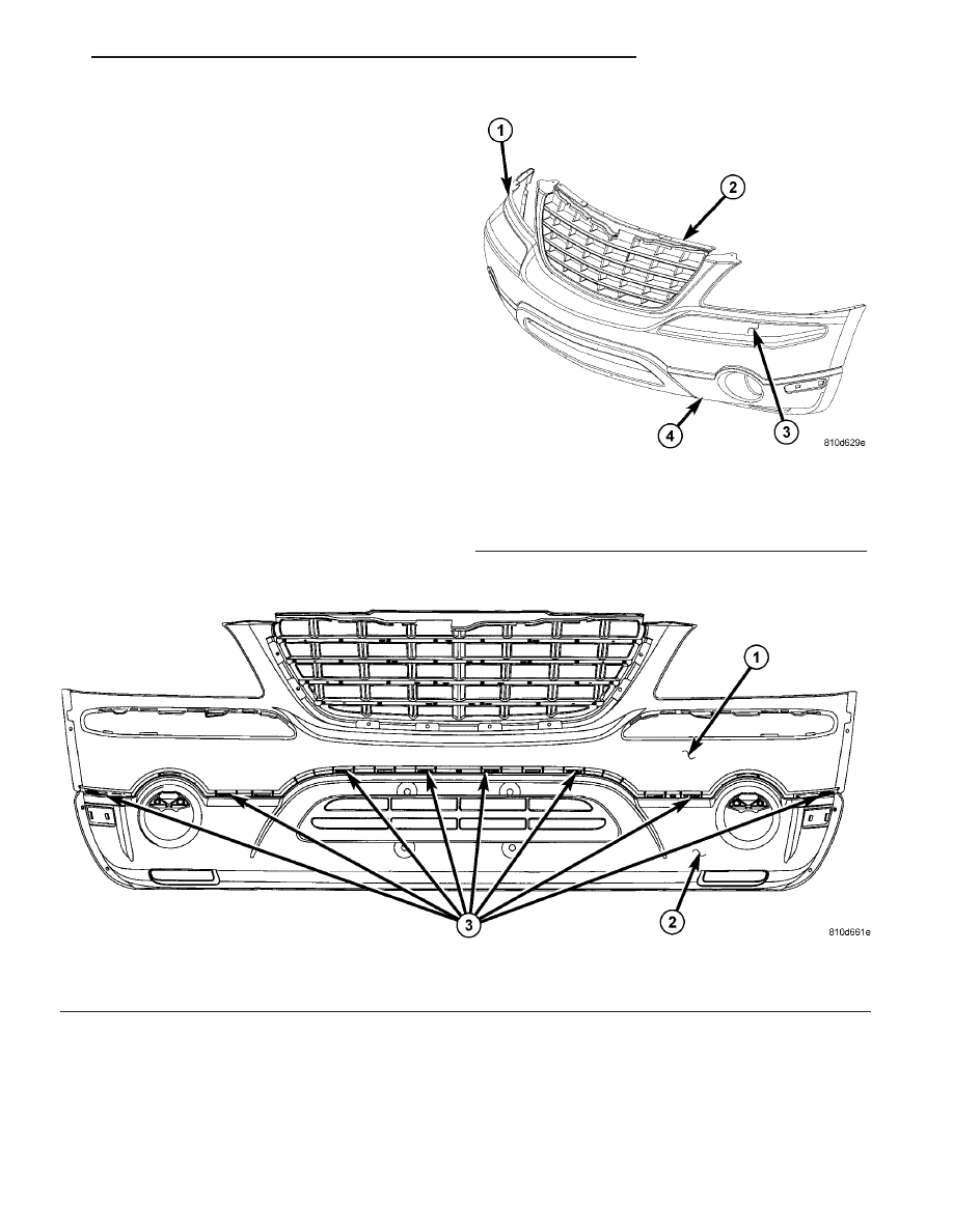
(12) Place fascia on a clean surface (Fig. 3).
(13) Remove spring clips attaching upper and

lower fascia together (Fig. 4).

(14) Using a trim stick release locking tabs and

separate the upper and lower fascia.

Fig. 3 UPPER AND LOWER FRONT FASCIA

1 - FRONT UPPER FASCIA
2 - GRILLE
3 - BRIGHT CHROME MOLDING
4 - FRONT LOWER FASCIA

Fig. 4 INTERLOCKING SEAM AND SPRING CLIPS

1 - FRONT UPPER FASCIA
2 - LOCKING TABS AND SPRING CLIPS

3 - FRONT LOWER FASCIA

CS

FRAME & BUMPERS

13 - 3

FRONT FASCIA (Continued)

(15) Remove the bright chrome molding from the

upper fascia (Fig. 5). Using a trim stick, starting at
the outer edge of the fascia release the locking tabs
(Fig. 6). Grip the molding and pull outward from the
fascia while releasing the locking tabs (Fig. 7).

(16) Remove molding from fascia.
(17) Remove grille from fascia. (Refer to 23 -

BODY/EXTERIOR/GRILLE - REMOVAL).

INSTALLATION

(1) Place bright chrome molding in position on the

upper fascia.

(2) Using hand presser press bright chrome mold-

ing locking tabs in the full lock position (Fig. 7).

(3) Position upper and lower fascia on a clean sur-

face so that locking tabs align with the slots (Fig. 3)
and (Fig. 4).

(4) Press the fascia together to lock locking tabs

into position.

(5) Install new spring clips attaching upper and

lower fascia together. The spring clips are not reusable.

(6) Place bumper fascia into position on vehicle.
(7) Install grille to fascia. (Refer to 23 - BODY/EX-

TERIOR/GRILLE - INSTALLATION).

(8) Install screw attaching the upper grille support

to the headlamp mounting panel at each side of the
grille.

(9) Install push pins attaching the upper appear-

ance panel to upper crossmember.

(10) Raise vehicle and support with safety stands,

as necessary.

(11) Connect fog lamp wire connectors, if necessary.
(12) Position and align fascia slotted cut out into

fender push fastener (Fig. 8).

(13) Install screw attaching fascia to the front

fenders on each side.

(14) Install front wheelhouse splash shields fasteners

as necessary (Refer to 23 - BODY/EXTERIOR/WHEEL-
HOUSE SPLASH SHIELD - INSTALLATION).

(15) Install front wheels.
(16) Install the four screws attaching bottom of

fascia/air dam to radiator closure panel.

Fig. 5 BRIGHT CHROME MOLDING LOCKING TABS

1 - UPPER AND LOWER FASCIA
2 - LOCKING TABS

Fig. 6 RELEASING LOCKING TABS

1 - FRONT UPPER FASCIA
2 - TRIM STICK
3 - BRIGHT CHROME MOLDING LOCKING TABS

Fig. 7 REMOVING BRIGHT CHROME MOLDING

1 - FRONT UPPER FASCIA
2 - PULL BRIGHT CHROME MOLDING

13 - 4

FRAME & BUMPERS

CS

FRONT FASCIA (Continued)

(17) Lower vehicle.
(18) Install the headlamp assemblies (Refer to 8 -

ELECTRICAL/LAMPS/LIGHTING

-

EXTERIOR/

HEADLAMP - INSTALLATION)

(19) Close hood.

FRONT LOWER FASCIA

DESCRIPTION

For Front Lower Fascia Procedures (Refer to 13 -

FRAME & BUMPERS/BUMPERS/FRONT FASCIA -
REMOVAL) and (Refer to 13 - FRAME & BUMPERS/
BUMPERS/FRONT FASCIA - INSTALLATION).

FRONT UPPER FASCIA

DESCRIPTION

For Front Upper Fascia Procedures (Refer to 13 -

FRAME & BUMPERS/BUMPERS/FRONT FASCIA -
REMOVAL) and (Refer to 13 - FRAME & BUMPERS/
BUMPERS/FRONT FASCIA - INSTALLATION).

REAR BUMPER
REINFORCEMENT BRACKET

REMOVAL

(1) Remove rear fascia. (Refer to 13 - FRAME &

BUMPERS/BUMPERS/REAR FASCIA - REMOVAL).

(2) Remove rear bumper reinforcement. (Refer to

13

-

FRAME

&

BUMPERS/BUMPERS/REAR

BUMPER REINFORCEMENT - REMOVAL).

(3) Remove two screws attaching reinforcement

bracket (left or right side) (Fig. 9) or (Fig. 10).

INSTALLATION

(1) Place reinforcement bracket into position.
(2) Install two screws attaching reinforcement

bracket (left or right side) (Fig. 9) or (Fig. 10).

(3) Tighten screws to 95 N·m (70 ft. lbs.) torque.
(4) Install rear bumper reinforcement (Refer to 13

- FRAME & BUMPERS/BUMPERS/REAR BUMPER
REINFORCEMENT - INSTALLATION).

Fig. 8 FASCIA ATTACHING FASTENER

1 - FASCIA ATTACHING FASTENER
2 - FRONT FENDER

Fig. 9 LEFT REINFORCEMENT BRACKET

1 - LEFT REINFORCEMENT BRACKET
2 - ATTACHING SCREWS AND WASHERS

Fig. 10 RIGHT REINFORCEMENT BRACKET

1 - RIGHT REINFORCEMENT BRACKET
2 - ATTACHING SCREWS AND WASHERS

CS

FRAME & BUMPERS

13 - 5

FRONT FASCIA (Continued)

(5) Install rear fascia. (Refer to 13 - FRAME &

BUMPERS/BUMPERS/REAR FASCIA - INSTALLA-
TION).

REAR BUMPER
REINFORCEMENT

REMOVAL

(1) Remove rear bumper fascia (Refer to 13 -

FRAME & BUMPERS/BUMPERS/REAR FASCIA -
REMOVAL).

(2) Support rear bumper reinforcement on a suit-

able lifting device.

(3) Remove the six nuts attaching rear bumper

reinforcement to frame rail extensions (Fig. 11).

(4) Remove rear bumper reinforcement from vehi-

cle.

INSTALLATION

(1) Support rear bumper reinforcement using a

suitable lifting device to lift into position.

(2) Position rear bumper reinforcement on vehicle.
(3) Install the six nuts attaching rear bumper rein-

forcement to frame rail extensions and tighten to 27
N·m (20 ft. lbs.) torque (Fig. 11).

(4) Install rear bumper fascia. (Refer to 13 -

FRAME & BUMPERS/BUMPERS/REAR FASCIA -
INSTALLATION).

REAR FASCIA

REMOVAL

(1) Open liftgate.
(2) Remove two push pin fasteners per side at the

liftgate tower area (Fig. 12).

(3) Hoist and support vehicle with safety stands,

as necessary.

Fig. 11 REAR BUMPER REINFORCEMENT

1 - REAR BUMPER REINFORCEMENT
2 - ATTACHING NUT(S)

Fig. 12 REAR FASCIA

1 - REAR FASCIA
2 - PUSH PIN FASTENERS
3 - SCREWS (2)

4 - CHECK ALIGNMENT
5 - SCREWS (2 PER SIDE)
6 - PUSH PINS (4)

13 - 6

FRAME & BUMPERS

CS

REAR BUMPER REINFORCEMENT BRACKET (Continued)


Content   ..  714  715  716  717   ..