Chrysler Pacifica. Manual - part 530
INSTALLATION
NOTE: Before starting this procedure, be certain
that the front wheels are in the straight-ahead posi-
tion.
(1) While holding the centered clockspring rotor
(Refer to 8 - ELECTRICAL/RESTRAINTS/CLOCK-
SPRING - STANDARD PROCEDURE - CLOCK-
SPRING
CENTERING)
and
case
stationary
in
relation to each other, carefully slide the clockspring
down over the steering column upper shaft.
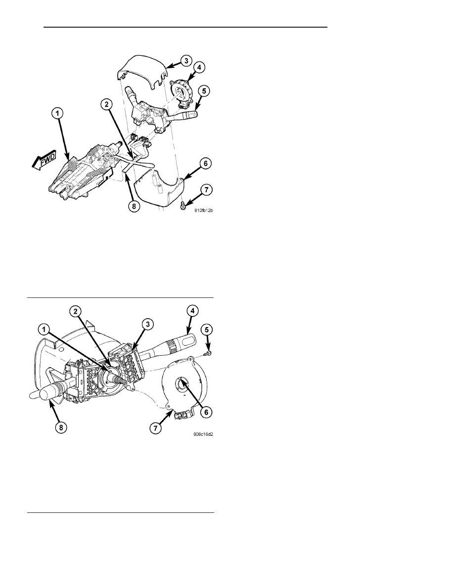
(2) Align and seat the three pins on the lower sur-
face of the clockspring rotor hub with the three holes
in the hub of the turn signal cancel cam (Fig. 12). It
should be noted that when the clockspring is prop-
erly centered the uppermost pin on the clockspring
rotor hub is the oblong pin, and it will only fit in the
oblong hole in the hub of the turn signal cancel cam.
(3) Align and seat the one pin and the two mount-
ing ears on the clockspring case to their respective
holes in the multi-function switch mounting housing.
(4) Install and tighten the two clockspring mount-
ing screws. Torque the screws to 2.5 N·m (22 in. lbs.).
(5) Connect the two instrument panel wire harness
connectors for the clockspring to the two connector
receptacles below the steering column on the back of
the clockspring housing.
(6) Install the upper and lower steering column
shrouds (Refer to 19 - STEERING/COLUMN/UPPER
SHROUD - INSTALLATION) and (Refer to 19 -
STEERING/COLUMN/LOWER SHROUD - INSTAL-
LATION) and (Fig. 11).
(7) Install and tighten the screw that secures the
lower tilting steering column shroud to the multi-
function switch mounting housing. Torque the screw
to 2 N·m (17 in. lbs.).
(8) If a new clockspring has been installed, remove
the plastic locking pin that secures the clockspring
rotor to the clockspring case to maintain clock spring
centering.
(9) Install the steering wheel onto the steering col-
umn. (Refer to 19 - STEERING/COLUMN/STEER-
ING WHEEL - INSTALLATION).
(10) Install the driver airbag onto the steering
wheel. (Refer to 8 - ELECTRICAL/RESTRAINTS/
DRIVER AIRBAG - INSTALLATION).
WARNING: DO NOT CONNECT THE BATTERY NEG-
ATIVE
CABLE.
(Refer
to
8
-
ELECTRICAL/RE-
STRAINTS - DIAGNOSIS AND TESTING - AIRBAG
SYSTEM) FIRST. FAILURE TO DO SO COULD
RESULT IN OCCUPANT PERSONAL INJURY OR
DEATH.
(11) Verify vehicle and system operation.
(12) Close hood.
Fig. 11 STEERING COLUMN SHROUDS - REMOVE/
INSTALL
1 - STEERING COLUMN
2 - WIRING HARNESS CLIP
3 - UPPER SHROUD
4 - CLOCKSPRING
5 - SWITCH MODULE
6 - LOWER SHROUD
7 - SHROUD MOUNTING SCREW
8 - WIRING HARNESS
Fig. 12 CLOCK SPRING - REMOVE/INSTALL
1 - OBLONG HOLE
2 - TURN SIGNAL CANCEL CAM
3 - MULTI-FUNCTION SWITCH MOUNTING HOUSING
4 - RIGHT MULTI-FUNCTION SWITCH
5 - SCREW (2)
6 - OBLONG PIN
7 - CLOCK SPRING
8 - LEFT MULTI-FUNCTION SWITCH
CS
RESTRAINTS
8O - 13
CLOCKSPRING (Continued)